Table 3−17. Function 5 Power-Management Registers
REGISTER NAME
OFFSET
44h
Power-management capabilities
Power-management control/status register bridge support extensions
Next item pointer
Capability ID
Data
Power-management control/status (CSR)
48h
3.8.9 CardBus Bridge Power Management
The PCI Bus Power Management Interface Specification for PCI to CardBus Bridges was approved by PCMCIA in
December of 1997. This specification follows the device and bus state definitions provided in the PCI Bus Power
Management Interface Specification published by the PCI Special Interest Group (SIG). The main issue addressed
in the PCI Bus Power Management Interface Specification for PCI to CardBus Bridges is wake-up from D3 or D3
without losing wake-up context (also called PME context).
hot
cold
The specific issues addressed by the PCI Bus Power Management Interface Specification for PCI to CardBus Bridges
for D3 wake-up are as follows:
•
Preservation of device context. The specification states that a reset must occur during the transition from
D3 to D0. Some method to preserve wake-up context must be implemented so that the reset does not clear
the PME context registers.
•
Power source in D3
if wake-up support is required from this state.
cold
The Texas Instruments PCI6x21/PCI6x11 controller addresses these D3 wake-up issues in the following manner:
•
•
Two resets are provided to handle preservation of PME context bits:
−
Global reset (GRST) is used only on the initial boot up of the system after power up. It places the
PCI6x21/PCI6x11 controller in its default state and requires BIOS to configure the controller before
becoming fully functional.
−
PCI reset (PRST) has dual functionality based on whether PME is enabled or not. If PME is enabled,
then PME context is preserved. If PME is not enabled, then PRST acts the same as a normal PCI reset.
Please see the master list of PME context bits in Section 3.8.11.
Power source in D3
auxiliary power source must be supplied to the PCI6x21/PCI6x11 V
if wake-up support is required from this state. Since V
is removed in D3
terminals. Consult the PCI14xx
, an
cold
CC
cold
CC
Implementation Guide for D3 Wake-Up or the PCI Power Management Interface Specification for PCI to
CardBus Bridges for further information.
3.8.10 ACPI Support
The Advanced Configuration and Power Interface (ACPI) Specification provides a mechanism that allows unique
pieces of hardware to be described to the ACPI driver. The PCI6x21/PCI6x11 controller offers a generic interface that
is compliant with ACPI design rules.
Two doublewords of general-purpose ACPI programming bits reside in PCI6x21/PCI6x11 PCI configuration space
at offset 88h. The programming model is broken into status and control functions. In compliance with ACPI, the top
level event status and enable bits reside in the general-purpose event status register (PCI offset 88h, see
Section 4.32) and general-purpose event enable register (PCI offset 89h, see Section 4.33). The status and enable
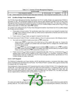
bits are implemented as defined by ACPI and illustrated in Figure 3−15.
Status Bit
Event Input
Event Output
Enable Bit
Figure 3−15. Block Diagram of a Status/Enable Cell
The status and enable bits generate an event that allows the ACPI driver to call a control method associated with the
pending status bit. The control method can then control the hardware by manipulating the hardware control bits or
3−25

 TI [ TEXAS INSTRUMENTS ]