Similarly, bus power states of the PCI bus are B0−B3. The bus power states B0−B3 are derived from the device power
state of the originating bridge device.
For the operating system (OS) to manage the controller power states on the PCI bus, the PCI function must support
four power-management operations. These operations are:
•
•
•
•
Capabilities reporting
Power status reporting
Setting the power state
System wake-up
The OS identifies the capabilities of the PCI function by traversing the new capabilities list. The presence of
capabilities in addition to the standard PCI capabilities is indicated by a 1 in bit 4 (CAPLIST) of the status register (PCI
offset 06h, see Section 4.5).
The capabilities pointer provides access to the first item in the linked list of capabilities. For the PCI6x21/PCI6x11
controller, a CardBus bridge with PCI configuration space header type 2, the capabilities pointer is mapped to an offset
of 14h. The first byte of each capability register block is required to be a unique ID of that capability. PCI power
management has been assigned an ID of 01h. The next byte is a pointer to the next pointer item in the list of
capabilities. If there are no more items in the list, then the next item pointer must be set to 0. The registers following
the next item pointer are specific to the capability of the function. The PCI power-management capability implements
the register block outlined in Table 3−14.
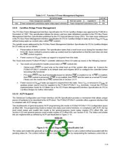
Table 3−14. Power-Management Registers
REGISTER NAME
Power-management capabilities
Power-management control/status register bridge support extensions
OFFSET
A0h
Next item pointer
Capability ID
Data
Power-management control/status (CSR)
A4h
The power-management capabilities register (PCI offset A2h, see Section 4.43) provides information on the
capabilities of the function related to power management. The power-management control/status register (PCI offset
A4h, see Section 4.44) enables control of power-management states and enables/monitors power-management
events. The data register is an optional register that can provide dynamic data.
For more information on PCI power management, see the PCI Bus Power Management Interface Specification for
PCI to CardBus Bridges.
3.8.8.2 Flash Media (Function 3) Power Management
The PCI Bus Power Management Interface Specification is applicable for the flash media dedicated sockets. This
function supports the D0 and D3 power states.
Table 3−15. Function 3 Power-Management Registers
REGISTER NAME
Power-management capabilities
Power-management control/status register bridge support extensions
OFFSET
44h
Next item pointer
Capability ID
Data
Power-management control/status (CSR)
48h
3.8.8.3 SD Host (Function 4) Power Management
The PCI Bus Power Management Interface Specification is applicable for the SD host dedicated sockets. This
function supports the D0 and D3 power states.
Table 3−16. Function 4 Power-Management Registers
REGISTER NAME
Power-management capabilities
Power-management control/status register bridge support extensions
OFFSET
80h
Next item pointer
Capability ID
Data
Power-management control/status (CSR)
84h
3.8.8.4 Smart Card (Function 5) Power Management
The PCI Bus Power Management Interface Specification is applicable for the Smart Card dedicated sockets. This
function supports the D0 and D3 power states.
3−24

 TI [ TEXAS INSTRUMENTS ]