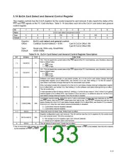
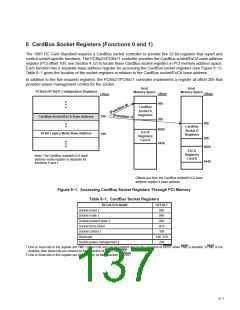
5.19 ExCA Card Detect and General Control Register
This register controls how the ExCA registers for the socket respond to card removal. It also reports the status of the
VS1 and VS2 signals at the PC Card interface. Table 5−14 describes each bit in the ExCA card detect and general
control register.
Bit
7
6
5
4
3
2
1
0
Name
Type
Default
ExCA card detect and general control
R
X
R
X
W
0
RW
0
R
0
R
0
RW
0
R
0
Register:
Offset:
ExCA card detect and general control
CardBus Socket Address + 816h:
Card A ExCA Offset 16h
Card B ExCA Offset 56h
Type:
Default:
Read-only, Write-only, Read/Write
XX00 0000b
Table 5−14. ExCA Card Detect and General Control Register Description
BIT
SIGNAL
TYPE
FUNCTION
VS2. This bit reports the current state of the VS2 signal at the PC Card interface, and, therefore, does not
have a default value.
7 †
VS2STAT
R
0 = VS2 is low.
1 = VS2 is high.
VS1. This bit reports the current state of the VS1 signal at the PC Card interface, and, therefore, does not
have a default value.
6 †
VS1STAT
SWCSC
R
0 = VS1 is low.
1 = VS1 is high.
Software card detect interrupt. If card detect enable, bit 3 in the ExCA card status change interrupt
configuration register (ExCA offset 805h, see Section 5.6) is set, then writing a 1 to this bit causes a
card-detect card-status-change interrupt for the associated card socket.
If the card-detect enable bit is cleared to 0 in the ExCA card status-change interrupt configuration register
(ExCA offset 805h, see Section 5.6), then writing a 1 to the software card-detect interrupt bit has no effect.
This bit is write-only.
5
W
A read operation of this bit always returns 0. Writing a 1 to this bit also clears it. If bit 2 of the ExCA global
control register (ExCA offset 81Eh, see Section 5.20) is set and a 1 is written to clear bit 3 of the ExCA
card status change interrupt register, then this bit also is cleared.
Card detect resume enable. If this bit is set to 1 and a card detect change has been detected on the CD1
and CD2 inputs, then the RI_OUT output goes from high to low. The RI_OUT remains low until the card
status change bit in the ExCA card status-change register (ExCA offset 804h, see Section 5.5) is cleared.
If this bit is a 0, then the card detect resume functionality is disabled.
4
CDRESUME
RW
0 = Card detect resume disabled (default)
1 = Card detect resume enabled
3−2
1
RSVD
REGCONFIG
RSVD
R
RW
R
These bits return 0s when read. Writes have no effect.
Register configuration upon card removal. This bit controls how the ExCA registers for the socket react
to a card removal event. This bit is encoded as:
0 = No change to ExCA registers upon card removal (default)
1 = Reset ExCA registers upon card removal
0
This bit returns 0 when read. A write has no effect.
†
One or more bits in this register are cleared only by the assertion of GRST when PME is enabled. If PME is not enabled, then this bit is cleared
by the assertion of PRST or GRST.
5−21

 TI [ TEXAS INSTRUMENTS ]