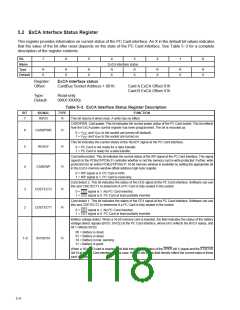
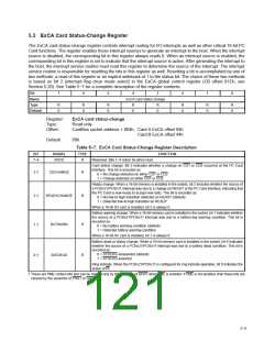
5.6 ExCA Card Status-Change Interrupt Configuration Register
This register controls interrupt routing for CSC interrupts, as well as masks/unmasks CSC interrupt sources. See
Table 5−8 for a complete description of the register contents.
Bit
7
6
5
4
3
2
1
0
Name
Type
Default
ExCA card status-change interrupt configuration
RW
0
RW
0
RW
0
RW
0
RW
0
RW
0
RW
0
RW
0
Register:
Offset:
ExCA card status-change interrupt configuration
CardBus Socket Address + 805h:
Card A ExCA Offset 05h
Card B ExCA Offset 45h
Type:
Default:
Read/Write
00h
Table 5−8. ExCA Card Status-Change Interrupt Configuration Register Description
BIT
SIGNAL
TYPE
FUNCTION
Interrupt select for card status change. These bits select the interrupt routing for card status-change
interrupts. This field is encoded as:
0000 = CSC interrupts routed to PCI interrupts if bit 5 of the diagnostic register (PCI offset 93h) is set
to 1b. In this case bit 4 of ExCA 803 is a don’t care. This is the default setting.
0000 = No ISA interrupt routing if bit 5 of the diagnostic register (PCI offset 93h) is set to 0b. In this case,
CSC interrupts are routed to PCI interrupts by setting bit 4 of ExCA 803h to 1b.
0001 = IRQ1 enabled
0010 = SMI enabled
0011 = IRQ3 enabled
0100 = IRQ4 enabled
0101 = IRQ5 enabled
7−4
CSCSELECT
RW
0110 = IRQ6 enabled
0111 = IRQ7 enabled
1000 = IRQ8 enabled
1001 = IRQ9 enabled
1010 = IRQ10 enabled
1011 = IRQ11 enabled
1100 = IRQ12 enabled
1101 = IRQ13 enabled
1110 = IRQ14 enabled
1111 = IRQ15 enabled
Card detect enable. Enables interrupts on CD1 or CD2 changes. This bit is encoded as:
3†
2†
CDEN
RW
RW
0 = Disables interrupts on CD1 or CD2 line changes (default)
1 = Enables interrupts on CD1 or CD2 line changes
Ready enable. This bit enables/disables a low-to-high transition on the PC Card READY signal to generate
a host interrupt. This interrupt source is considered a card status change. This bit is encoded as:
READYEN
0 = Disables host interrupt generation (default)
1 = Enables host interrupt generation
Battery warning enable. This bit enables/disables a battery warning condition to generate a CSC interrupt.
This bit is encoded as:
1†
0†
BATWARNEN
BATDEADEN
RW
RW
0 = Disables host interrupt generation (default)
1 = Enables host interrupt generation
Battery dead enable. This bit enables/disables a battery dead condition on a memory PC Card or assertion
of the STSCHG I/O PC Card signal to generate a CSC interrupt.
0 = Disables host interrupt generation (default)
1 = Enables host interrupt generation
†
This bit is cleared only by the assertion of GRST when PME is enabled. If PME is not enabled, then this bit is cleared by the assertion of PRST
or GRST.
5−10

 TI [ TEXAS INSTRUMENTS ]