ONET1131EC
www.ti.com.cn
ZHCSFG0 –SEPTEMBER 2016
10 Layout
10.1 Layout Guidelines
For optimum performance, use 50-Ω transmission lines (100-Ω differential) for connecting the high speed inputs
and outputs. The length of transmission lines should be kept as short as possible to reduce loss and pattern-
dependent jitter.
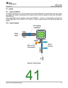
If the single-ended mode of operation is being used (TXMODE = 1) then it is recommended to terminate the
unused output with a 50-Ω resistor to VCC. Figure 54 shows a typical layout for the high speed inputs and
outputs.
10.2 Layout Example
!/-coupling
capacitors
ÇóLb+
Crom
Iost
ÇóLb-
ÇóhÜÇ-
.ias-Ç
Cerrites
50O to ë//
Çermination
Figure 54. Board Layout
版权 © 2016, Texas Instruments Incorporated
41

 TI [ TEXAS INSTRUMENTS ]