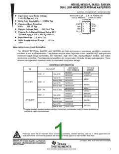
ꢀꢁ ꢂꢂ ꢃ ꢄ ꢅ ꢀꢁ ꢂꢂ ꢃ ꢄ ꢆꢅ ꢇꢆ ꢂꢂ ꢃ ꢄ ꢅ ꢇ ꢆꢂ ꢂꢃ ꢄꢆ
ꢈꢉꢆ ꢊ ꢊ ꢋ ꢌꢍꢀꢋ ꢎꢇ ꢁ ꢋ ꢏꢁꢐ ꢆꢑ ꢎꢋ ꢀꢆꢊ ꢆꢒ ꢏ ꢊꢎ ꢓꢎ ꢁꢐ ꢇ
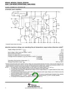
SLOS075H − NOVEMBER 1979 − REVISED MAY 2004
recommended operating conditions
MIN
5
MAX
15
UNIT
V
V
V
Supply voltage
Supply voltage
CC+
−5
0
−15
70
V
CC−
NE5532, NE5532A
SA5532, SA5532A
T
A
Operating free-air temperature range
°C
−40
85
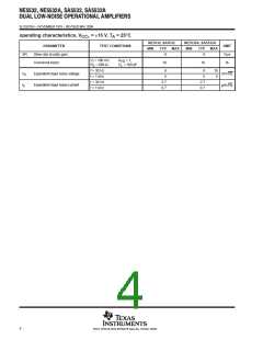
electrical characteristics, V
= +15 V, T = 25°C (unless otherwise noted)
A
CC
NE5532, NE5532A
SA5532, SA5532A
†
PARAMETER
TEST CONDITIONS
UNIT
MIN
TYP
MAX
4
T
= 25°C
0.5
A
V
Input offset voltage
Input offset current
Input bias current
V
= 0
mV
nA
IO
O
‡
T
A
= Full range
5
T
A
= 25°C
10
150
200
800
1000
I
IO
‡
‡
T
A
= Full range
= 25°C
T
A
200
I
IB
nA
V
T
A
= Full range
V
ICR
Common-mode input-voltage range
12
24
30
15
10
25
15
13
26
32
50
V
V
=
=
15 V
18 V
CC
Maximum peak-to-peak
output-voltage swing
V
OPP
R
≥ 600 Ω
≥ 600 Ω,
V
L
L
CC
T
A
= 25°C
R
V
‡
‡
=
10 V
T
= Full range
= 25°C
A
O
Large-signal
differential-voltage amplification
A
A
VD
V/mV
T
100
R
≥ 2 kΩ,
= 10 V
L
V
O
T
A
= Full range
Small-signal
differential-voltage amplification
A
f = 10 kHz
2.2
V/mV
kHz
vd
V
V
=
10 V
18 V,
140
100
10
O
B
B
Maximum-output-swing bandwidth
R
R
= 600 Ω
= 600 Ω,
OM
L
L
=
V
= 14 V
CC
O
Unity-gain bandwidth
Input resistance
C
= 100 pF
MHz
kΩ
Ω
1
L
L
r
30
300
0.3
100
i
z
Output impedance
A
VD
= 30 dB,
R
= 600 Ω,
f = 10 kHz
o
CMRR Common-mode rejection ratio
V
IC
= V
ICR
min
70
80
10
dB
Supply-voltage rejection ratio
k
V
CC
=
9 V to 15 V,
V = 0
O
100
dB
SVR
(∆V
CC
/∆V )
IO
I
I
Output short-circuit current
Total supply curent
38
8
60
16
mA
mA
dB
OS
V
V
= 0,
No load
CC
O
Crosstalk attenuation (V /V
)
= 10 V peak, f = 1 kHz
110
O1 O2
01
†
‡
All characteristics are measured under open-loop conditions, with zero common-mode input voltage, unless otherwise specified.
Full temperature ranges are: −40°C to 85°C for the SA5532 and SA5532A, and 0°C to 70°C for the NE5532 and NE5532A.
3
POST OFFICE BOX 655303 • DALLAS, TEXAS 75265

 TI [ TEXAS INSTRUMENTS ]