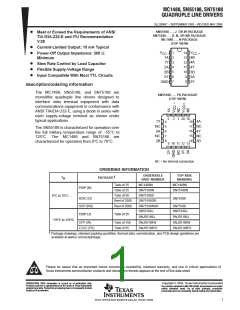
ꢀ ꢁꢂ ꢃ ꢄ ꢄ ꢅ ꢆꢇ ꢈꢈ ꢂ ꢄ ꢄ ꢅ ꢆ ꢇꢉ ꢈꢂ ꢄꢄ
ꢊ ꢋꢌꢍꢎ ꢋꢏꢐ ꢑ ꢐ ꢒꢇꢑ ꢍ ꢎꢒ ꢓ ꢑꢎ ꢆ
SLLS094C − SEPTEMBER 1983 − REVISED MAY 2004
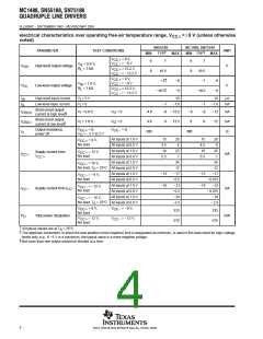
switching characteristics, V
= 9 V, T = 25°C
A
CC
PARAMETER
TEST CONDITIONS
MIN
TYP
220
100
55
MAX
350
175
100
75
UNIT
ns
t
t
t
t
t
t
Propagation delay time, low- to high-level output
PLH
PHL
TLH
THL
TLH
THL
Propagation delay time, high- to low-level output
ns
R
= 3 kΩ,
See Figure 1
C
C
= 15 pF,
L
L
L
†
Transition time, low- to high-level output
ns
†
‡
‡
Transition time, high- to low-level output
Transition time, low- to high-level output
Transition time, high- to low-level output
45
ns
2.5
3.0
µs
R
= 3 kΩ to 7 kΩ,
= 2500 pF,
L
See Figure 1
µs
†
‡
Measured between 10% and 90% points of output waveform
Measured between 3 V and −3 V points on the output waveform (TIA/EIA-232-E conditions)
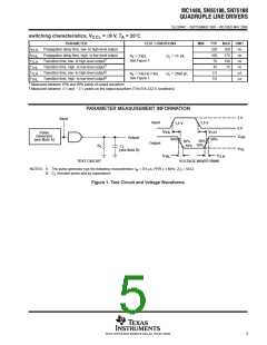
PARAMETER MEASUREMENT INFORMATION
3 V
0 V
Input
Input
1.5 V
1.5 V
t
t
PHL
90%
PLH
90%
Pulse
Generator
(see Note A)
V
OH
OL
Output
50%
10%
50%
10%
Output
R
C
L
L
V
(see Note B)
t
t
THL
TLH
TEST CIRCUIT
VOLTAGE WAVEFORMS
NOTES: A. The pulse generator has the following characteristics: t = 0.5 µs, PRR ≤ 1 MHz, Z = 50 Ω.
w
O
B.
C includes probe and jig capacitance.
L
Figure 1. Test Circuit and Voltage Waveforms
5
POST OFFICE BOX 655303 • DALLAS, TEXAS 75265

 TI [ TEXAS INSTRUMENTS ]