LMV331-N, LMV339-N, LMV393-N
SNOS018G –AUGUST 1999–REVISED FEBRUARY 2013
www.ti.com
(13)
Where Vmax is the max applied potential across the capacitor = (2VCC/3)
and VC = Vmax/2 = VCC/3
One period will be given by:
1/freq = 2t
(14)
(15)
or calculating the exponential gives:
1/freq = 2(0.694) R4 C1
Resistors R3 and R4 must be at least two times larger than R5 to insure that VO will go all the way up to VCC in
the high state. The frequency stability of this circuit should strictly be a function of the external components.
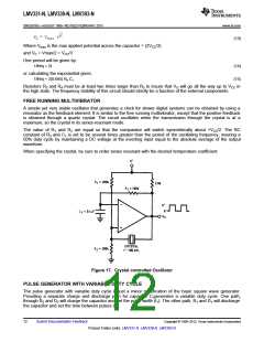
FREE RUNNING MULTIVIBRATOR
A simple yet very stable oscillator that generates a clock for slower digital systems can be obtained by using a
resonator as the feedback element. It is similar to the free running multivibrator, except that the positive feedback
is obtained through a quartz crystal. The circuit oscillates when the transmission through the crystal is at a
maximum, so the crystal in its series-resonant mode.
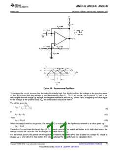
The value of R1 and R2 are equal so that the comparator will switch symmetrically about +VCC/2. The RC
constant of R3 and C1 is set to be several times greater than the period of the oscillating frequency, insuring a
50% duty cycle by maintaining a DC voltage at the inverting input equal to the absolute average of the output
waveform.
When specifying the crystal, be sure to order series resonant with the desired temperature coefficient.
Figure 17. Crystal controlled Oscillator
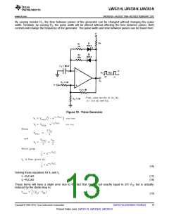
PULSE GENERATOR WITH VARIABLE DUTY CYCLE
The pulse generator with variable duty cycle is just a minor modification of the basic square wave generator.
Providing a separate charge and discharge path for capacitor C1generates a variable duty cycle. One path,
through R2 and D2 will charge the capacitor and set the pulse width (t1). The other path, R1 and D1 will discharge
the capacitor and set the time between pulses (t2).
12
Submit Documentation Feedback
Copyright © 1999–2013, Texas Instruments Incorporated
Product Folder Links: LMV331-N LMV339-N LMV393-N

 TI [ TEXAS INSTRUMENTS ]