LMV331-N, LMV339-N, LMV393-N
www.ti.com
SNOS018G –AUGUST 1999–REVISED FEBRUARY 2013
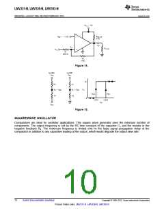
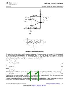
Figure 16. Squarewave Oscillator
To analyze the circuit, assume that the output is initially high. For this to be true, the voltage at the inverting input
Vc has to be less than the voltage at the non-inverting input Va. For Vc to be low, the capacitor C1 has to be
discharged and will charge up through the negative feedback resistor R4. When it has charged up to value equal
to the voltage at the positive input Va1, the comparator output will switch.
Va1 will be given by:
(9)
If:
Then:
R1 = R2 = R3
(10)
(11)
(12)
Va1 = 2VCC/3
When the output switches to ground, the value of Va is reduced by the hysteresis network to a value given by:
Va2 = VCC/3
Capacitor C1 must now discharge through R4 towards ground. The output will return to its high state when the
voltage across the capacitor has discharged to a value equal to Va2.
For the circuit shown, the period for one cycle of oscillation will be twice the time it takes for a single RC circuit to
charge up to one half of its final value. The time to charge the capacitor can be calculated from
Copyright © 1999–2013, Texas Instruments Incorporated
Submit Documentation Feedback
11
Product Folder Links: LMV331-N LMV339-N LMV393-N

 TI [ TEXAS INSTRUMENTS ]