POWER CONSUMPTION
-Deep Sleep mode is not used
The LMP91000 is intended for use in portable devices, so the
power consumption is as low as possible in order to guarantee
a long battery life. The total power consumption for the
LMP91000 is below 10µA @ 3.3v average over time, (this
excludes any current drawn from any pin). A typical usage of
the LMP91000 is in a portable gas detector and its power
consumption is summarized in the Power Consumption Sce-
nario table. This has the following assumptions:
-The system is used about 8 hours a day, and 16 hours a day
it is in Standby mode.
-Temperature Measurement is done about once per minute
This results in an average power consumption of approxi-
mately 7.95 µA. This can potentially be further reduced, by
using the Standby mode between gas measurements. It may
even be possible, depending on the sensor used, to go into
deep sleep for some time between measurements, further
reducing the average power consumption.
-Power On only happens a few times over life, so its power
consumption can be ignored
Power Consumption Scenario
3-Lead
Temperature
Temperature
Deep Sleep
StandBy
Amperometric Measurement Measurement Total
Cell
TIA OFF
TIA ON
Current consumption
(µA)
typical value
0.6
0
6.5
60
10
39
3.9
11.4
0
14.9
1
Time ON
(%)
Average
(µA)
0
3.9
0
0.15
7.95
Notes
A1
OFF
OFF
OFF
ON
ON
ON
ON
OFF
ON
ON
OFF
ON
ON
ON
ON
ON
ON
TIA
OFF
OFF
ON
TEMP SENSOR
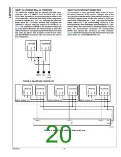
I2C interface
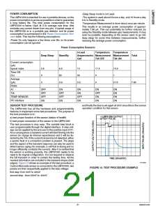
SENSOR TEST PROCEDURE
and finally the bias is set again at 0mV since this is the normal
operation condition for this sensor.
The LMP91000 has all the hardware and programmability
features to implement some test procedures. The purpose of
the test procedure is to:
LMP91000 OUTPUT
TEST PULSE
a) test proper function of the sensor (status of health)
b) test proper connection of the sensor to the LMP91000
The test procedure is very easy. The variable bias block is
user programmable through the digital interface. A step volt-
age can be applied by the end user to the positive input of A1.
As a consequence a transient current will start flowing into the
sensor (to charge its internal capacitance) and it will be de-
tected by the TIA. If the current transient is not detected, either
a sensor fault or a connection problem is present. The slope
and the aspect of the transient response can also be used to
detect sensor aging (for example, a cell that is drying and no
longer efficiently conducts the current). After it is verified that
the sensor is working properly, the LMP91000 needs to be
reset to its original configuration. It is not required to observe
the full transient in order to contain the testing time. All the
needed information are included in the transient slopes (both
edges). Figure 10 shows an example of the test procedure, a
Carbon Monoxide sensor is connected to the LMP91000, two
pulses are then sequentially applied to the bias voltage:
TIME (25ms/DIV)
30132561
FIGURE 10. TEST PROCEDURE EXAMPLE
first step: from 0mV to 40mV
second step : from 40mV to -40mV
21
www.ti.com

 TI [ TEXAS INSTRUMENTS ]