30132575
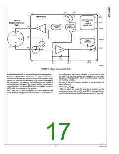
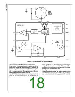
FIGURE 5. 2-Lead Galvanic Cell Ground Referred
2-lead Galvanic Cell In Potentiostat Configuration
Control Amplifier (A1) is ON and provides the internal zero
voltage. The transimpedance amplifier (TIA) is also ON, it
converts the current generated by the gas sensor in a voltage,
according to the transimpedance gain:
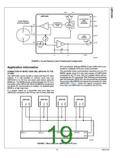
When the LMP91000 is interfaced to a galvanic cell (for in-
stance to an Oxygen gas sensor) referred to a reference, the
Counter and the Reference pin of the LMP91000 are shorted
together and connected to negative electrode of the galvanic
cell. The positive electrode of the galvanic cell is then con-
nected to the Working pin of the LMP91000.
Gain= RTIA
If different gains are required, an external resistor can be
connected between the pins C1 and C2. In this case the in-
ternal feedback resistor should be programmed to “external”.
The LMP91000 is then configured in 3-lead amperometric cell
mode (as for amperometric cell). In this configuration the
www.ti.com
18

 TI [ TEXAS INSTRUMENTS ]