30132584
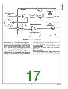
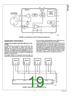
FIGURE 6. 2-Lead Galvanic Cell In Potentiostat Configuration
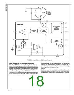
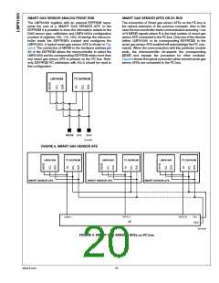
SCL) are shared, while the MENB of each LMP91000 is con-
nected to a dedicate GPIO port of the μcontroller.
Application Information
The μcontroller starts communication asserting one out of N
MENB signals where N is the total number of LMP91000s
connected to the I2C bus. Only the enabled device will ac-
knowledge the I2C commands. After finishing communicating
with this particular LMP91000, the microcontroller de-asserts
the corresponding MENB and repeats the procedure for other
LMP91000s. Figure 7 shows the typical connection when
more than one LMP91000 is connected to the I2C bus.
CONNECTION OF MORE THAN ONE LMP91000 TO THE
I2C BUS
The LMP91000 comes out with a unique and fixed I2C slave
address. It is still possible to connect more than one
LMP91000 to an I2C bus and select each device using the
MENB pin. The MENB simply enables/disables the I2C com-
munication of the LMP91000. When the MENB is at logic level
low all the I2C communication is enabled, it is disabled when
MENB is at high logic level.
In a system based on a μcontroller and more than one
LMP91000 connected to the I2C bus, the I2C lines (SDA and
30132581
FIGURE 7. More than one LMP91000 on I2C bus
19
www.ti.com

 TI [ TEXAS INSTRUMENTS ]