LMH0324
www.ti.com.cn
ZHCSIC8B –APRIL 2016–REVISED JUNE 2018
6.6 Recommended SMBus Interface AC Timing Specifications
over recommended operating supply and temperature ranges (unless otherwise noted)
(1)(2) (3)
MIN
NOM
MAX
UNIT
FSCL
TBUF
SMBus SCL Frequency
10
400
kHz
Bus Free Time between Stop and
Start Condition
1.3
0.6
0.6
µs
µs
µs
Hold time after (Repeated) Start
Condition. After this period, the first
clock is generated.
THD:STA
Repeated Start Condition Setup
Time
TSU:STA
TSU:STO
THD:DAT
TSU:DAT
TLOW
THIGH
TR
Stop Condition Setup Time
Data Hold Time
0.6
0
µs
ns
ns
µs
µs
ns
ns
Data Setup Time
100
1.3
0.6
Clock Low Period
Clock High Period
Clock/Data Rise Time
Clock/Data Fall Time
300
300
TF
(1) These parameters support SMBus 2.0 specifications.
(2) These parameters are not production tested.
(3) See Figure 1 for timing diagrams.
6.7 Serial Parallel Interface (SPI) AC Timing Specifications
over recommended operating supply and temperature ranges (unless otherwise noted)(1)
MIN
NOM
MAX
20
UNIT
MHz
ns
FSCK
TSCK
TPH
SPI SCK Frequency
SCK Period
10
50
SCK Pulse Width High
SCK Pulse Width Low
MOSI Setup Time
0.40 x TSCK
ns
TPL
0.40 x TSCK
ns
TSU
4
4
ns
TH
MOSI Hold Time
ns
TSSSU
TSSH
TSSOF
TODZ
TOZD
TOD
SS_N Setup Time
14
4
ns
SS_N Hold Time
ns
SS_N Off Time
1
µs
MISO Driven-to-Tristate Time
MISO Tristate-to-Driven Time
MISO Output Delay Time
20
10
15
ns
ns
ns
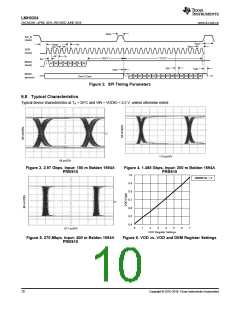
(1) See Figure 2 for timing diagrams.
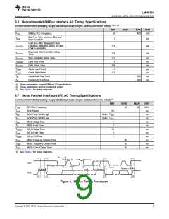
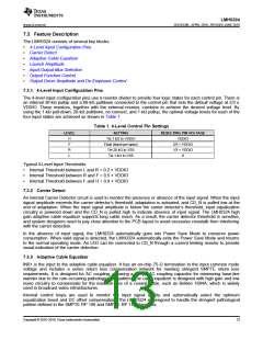
ttLOW
t
tR
tHIGH
SCL
ttHD:STA
t
tHD:DAT
tSU:STA
tF
tSU:STO
ttBUF
t
tSU:DAT
SDA
SP
ST
ST
SP
Figure 1. SMBus Timing Parameters
Copyright © 2016–2018, Texas Instruments Incorporated
9

 TI [ TEXAS INSTRUMENTS ]