LM555
www.ti.com
SNAS548C –FEBRUARY 2000–REVISED MARCH 2013
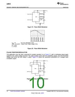
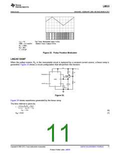
VCC = 5V
Top Trace: Modulation Input 1V/Div.
Bottom Trace: Output 2V/Div.
TIME = 0.1 ms/DIV.
RA = 3.9kΩ
RB = 3kΩ
C = 0.01μF
Figure 22. Pulse Position Modulator
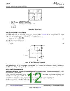
LINEAR RAMP
When the pullup resistor, RA, in the monostable circuit is replaced by a constant current source, a linear ramp is
generated. Figure 23 shows a circuit configuration that will perform this function.
Figure 23.
Figure 24 shows waveforms generated by the linear ramp.
The time interval is given by:
(6)
VBE ≃ 0.6V
(7)
Copyright © 2000–2013, Texas Instruments Incorporated
Submit Documentation Feedback
11
Product Folder Links: LM555

 TI [ TEXAS INSTRUMENTS ]