LM555
SNAS548C –FEBRUARY 2000–REVISED MARCH 2013
www.ti.com
Figure 19. Pulse Width Modulator
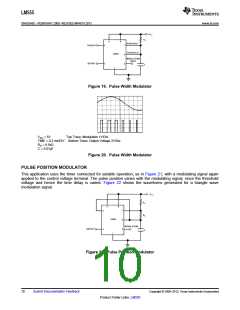
VCC = 5V
Top Trace: Modulation 1V/Div.
TIME = 0.2 ms/DIV. Bottom Trace: Output Voltage 2V/Div.
RA = 9.1kΩ
C = 0.01μF
Figure 20. Pulse Width Modulator
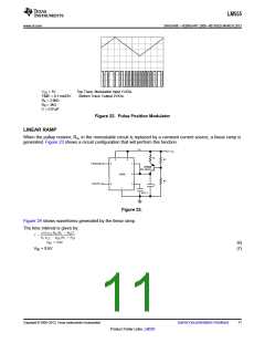
PULSE POSITION MODULATOR
This application uses the timer connected for astable operation, as in Figure 21, with a modulating signal again
applied to the control voltage terminal. The pulse position varies with the modulating signal, since the threshold
voltage and hence the time delay is varied. Figure 22 shows the waveforms generated for a triangle wave
modulation signal.
Figure 21. Pulse Position Modulator
10
Submit Documentation Feedback
Copyright © 2000–2013, Texas Instruments Incorporated
Product Folder Links: LM555

 TI [ TEXAS INSTRUMENTS ]