LM2672
SNVS136K –SEPTEMBER 1998–REVISED APRIL 2013
www.ti.com
Application Information
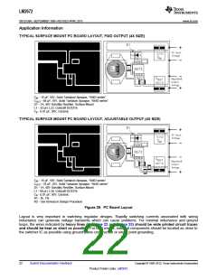
TYPICAL SURFACE MOUNT PC BOARD LAYOUT, FIXD OUTPUT (4X SIZE)
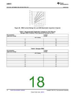
CIN - 15 μF, 50V, Solid Tantalum Sprague, “594D series”
COUT - 68 μF, 16V, Solid Tantalum Sprague, “594D series”
D1 - 1A, 40V Schottky Rectifier, Surface Mount
L1 - 33 μH, L23, Coilcraft DO3316
CB - 0.01 μF, 50V, Ceramic
TYPICAL SURFACE MOUNT PC BOARD LAYOUT, ADJUSTABLE OUTPUT (4X SIZE)
CIN - 15 μF, 50V, Solid Tantalum Sprague, “594D series”
COUT - 33 μF, 25V, Solid Tantalum Sprague, “594D series”
D1 - 1A, 40V Schottky Rectifier, Surface Mount
L1 - 68 μH, L30, Coilcraft DO3316
CB - 0.01 μF, 50V, Ceramic
R1 - 1k, 1%
R2 - Use formula in Design Procedure
Figure 29. PC Board Layout
Layout is very important in switching regulator designs. Rapidly switching currents associated with wiring
inductance can generate voltage transients which can cause problems. For minimal inductance and ground
loops, the wires indicated by heavy lines (in Figure 22 and Figure 23) should be wide printed circuit traces
and should be kept as short as possible. For best results, external components should be located as close to
the switcher IC as possible using ground plane construction or single point grounding.
22
Submit Documentation Feedback
Copyright © 1998–2013, Texas Instruments Incorporated
Product Folder Links: LM2672

 TI [ TEXAS INSTRUMENTS ]