LM2672
www.ti.com
SNVS136K –SEPTEMBER 1998–REVISED APRIL 2013
PROCEDURE (Fixed Output Voltage Version)
2. Output Capacitor Selection (COUT
A. Select an output capacitor from the output capacitor table in
EXAMPLE (Fixed Output Voltage Version)
)
2. Output Capacitor Selection (COUT
)
A. Use the 5.0V section in the output capacitor table in Table 3.
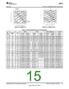
Table 3. Using the output voltage and the inductance value found in Choose a capacitor value and voltage rating from the line that
the inductor selection guide, step 1, locate the appropriate capacitor contains the inductance value of 33 μH. The capacitance and
value and voltage rating.
voltage rating values corresponding to the 33 μH
The capacitor list contains through-hole electrolytic capacitors from
four different capacitor manufacturers and surface mount tantalum
capacitors from two different capacitor manufacturers. It is
recommended that both the manufacturers and the manufacturer's
series that are listed in the table be used. A table listing the
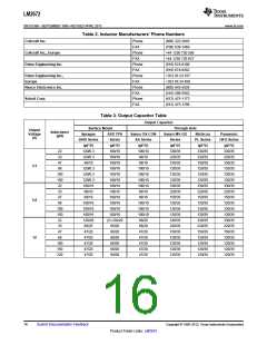
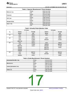
manufacturers' phone numbers is located in Table 4.
Surface Mount:
68 μF/10V Sprague 594D Series.
100 μF/10V AVX TPS Series.
Through Hole:
68 μF/10V Sanyo OS-CON SA Series.
220 μF/35V Sanyo MV-GX Series.
220 μF/35V Nichicon PL Series.
220 μF/35V Panasonic HFQ Series.
3. Catch Diode Selection (D1)
3. Catch Diode Selection (D1)
A. In normal operation, the average current of the catch diode is the A. Refer to the table shown in Table 5. In this example, a 1A, 20V
load current times the catch diode duty cycle, 1-D (D is the switch
duty cycle, which is approximately the output voltage divided by the
input voltage). The largest value of the catch diode average current
occurs at the maximum load current and maximum input voltage
(minimum D). For normal operation, the catch diode current rating
must be at least 1.3 times greater than its maximum average
current. However, if the power supply design must withstand a
continuous output short, the diode should have a current rating equal
to the maximum current limit of the LM2672. The most stressful
condition for this diode is a shorted output condition.
Schottky diode will provide the best performance. If the circuit must
withstand a continuous shorted output, a higher current Schottky
diode is recommended.
B. The reverse voltage rating of the diode should be at least 1.25
times the maximum input voltage.
C. Because of their fast switching speed and low forward voltage
drop, Schottky diodes provide the best performance and efficiency.
This Schottky diode must be located close to the LM2672 using
short leads and short printed circuit traces.
4. Input Capacitor (CIN
A low ESR aluminum or tantalum bypass capacitor is needed
between the input pin and ground to prevent large voltage transients voltage rating and the RMS current rating. With a maximum input
from appearing at the input. This capacitor should be located close voltage of 12V, an aluminum electrolytic capacitor with a voltage
to the IC using short leads. In addition, the RMS current rating of the rating greater than 15V (1.25 × VIN) would be needed. The next
)
4. Input Capacitor (CIN
)
The important parameters for the input capacitor are the input
input capacitor should be selected to be at least ½ the DC load
current. The capacitor manufacturer data sheet must be checked to
higher capacitor voltage rating is 16V.
The RMS current rating requirement for the input capacitor in a buck
assure that this current rating is not exceeded. The curves shown in regulator is approximately ½ the DC load current. In this example,
Figure 28 show typical RMS current ratings for several different
aluminum electrolytic capacitor values. A parallel connection of two
or more capacitors may be required to increase the total minimum
RMS current rating to suit the application requirements.
For an aluminum electrolytic capacitor, the voltage rating should be
at least 1.25 times the maximum input voltage. Caution must be
exercised if solid tantalum capacitors are used. The tantalum
with a 1A load, a capacitor with a RMS current rating of at least 500
mA is needed. The curves shown in Figure 28 can be used to select
an appropriate input capacitor. From the curves, locate the 16V line
and note which capacitor values have RMS current ratings greater
than 500 mA.
For a through hole design, a 330 μF/16V electrolytic capacitor
(Panasonic HFQ series, Nichicon PL, Sanyo MV-GX series or
capacitor voltage rating should be twice the maximum input voltage. equivalent) would be adequate. Other types or other manufacturers'
The tables in Table 7 show the recommended application voltage for capacitors can be used provided the RMS ripple current ratings are
AVX TPS and Sprague 594D tantalum capacitors. It is also
adequate. Additionally, for a complete surface mount design,
recommended that they be surge current tested by the manufacturer. electrolytic capacitors such as the Sanyo CV-C or CV-BS and the
The TPS series available from AVX, and the 593D and 594D series Nichicon WF or UR and the NIC Components NACZ series could be
from Sprague are all surge current tested. Another approach to
minimize the surge current stresses on the input capacitor is to add
a small inductor in series with the input supply line.
Use caution when using ceramic capacitors for input bypassing,
because it may cause severe ringing at the VIN pin.
considered.
For surface mount designs, solid tantalum capacitors can be used,
but caution must be exercised with regard to the capacitor surge
current rating and voltage rating. In this example, checking Table 7,
and the Sprague 594D series datasheet, a Sprague 594D 15 μF,
25V capacitor is adequate.
5. Boost Capacitor (CB)
5. Boost Capacitor (CB)
This capacitor develops the necessary voltage to turn the switch
gate on fully. All applications should use a 0.01 μF, 50V ceramic
capacitor.
For this application, and all applications, use a 0.01 μF, 50V ceramic
capacitor.
Copyright © 1998–2013, Texas Instruments Incorporated
Submit Documentation Feedback
13
Product Folder Links: LM2672

 TI [ TEXAS INSTRUMENTS ]