LM2672
SNVS136K –SEPTEMBER 1998–REVISED APRIL 2013
www.ti.com
ON/OFF
This input provides an electrical ON/OFF control of the power supply. Connecting this pin to ground or to any
voltage less than 0.8V will completely turn OFF the regulator. The current drain from the input supply when OFF
is only 50μA. The ON/OFF input has an internal pull-up current source of approximately 20μA and a protection
clamp zener diode of 7V to ground. When electrically driving the ON/OFF pin the high voltage level for the ON
condition should not exceed the 6V absolute maximum limit. When ON/OFF control is not required this pin
should be left open.
DAP (WSON PACKAGE)
The Die Attach Pad (DAP) can and should be connected to the PCB Ground plane/island. For CAD and
assembly guidelines refer to Application Note SNAO401 at http://www.ti.com/lit/an/snoa401/snoa401.pdf.
LM2672 Series Buck Regulator Design Procedure (Fixed Output)
PROCEDURE (Fixed Output Voltage Version)
EXAMPLE (Fixed Output Voltage Version)
To simplify the buck regulator design procedure, Texas Instruments
is making available computer design software to be used with the
SIMPLE SWITCHER line of switching regulators.LM267X Made
Simple version 6.0 is available on Windows® 3.1, NT, or 95
operating systems.
Given:
Given:
VOUT = 5V
VOUT = Regulated Output Voltage (3.3V, 5V, or 12V)
VIN(max) = Maximum DC Input Voltage
ILOAD(max) = Maximum Load Current
VIN(max) = 12V
ILOAD(max) = 1A
1. Inductor Selection (L1)
1. Inductor Selection (L1)
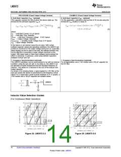
A. Select the correct inductor value selection guide from Figure 24
and Figure 25 or Figure 26 (output voltages of 3.3V, 5V, or 12V
respectively). For all other voltages, see the design procedure for the
adjustable version.
A. Use the inductor selection guide for the 5V version shown in
Figure 25.
B. From the inductor value selection guide, identify the inductance
region intersected by the Maximum Input Voltage line and the
Maximum Load Current line. Each region is identified by an
inductance value and an inductor code (LXX).
B. From the inductor value selection guide shown in Figure 25, the
inductance region intersected by the 12V horizontal line and the 1A
vertical line is 33 μH, and the inductor code is L23.
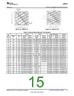
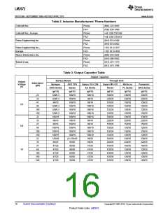
C. Select an appropriate inductor from the four manufacturer's part
C. The inductance value required is 33 μH. From the table in
numbers listed in Table 1. Each manufacturer makes a different style Table 1, go to the L23 line and choose an inductor part number from
of inductor to allow flexibility in meeting various design requirements. any of the four manufacturers shown. (In most instances, both
Listed below are some of the differentiating characteristics of each
manufacturer's inductors:
through hole and surface mount inductors are available.)
Schott: ferrite EP core inductors; these have very low leakage
magnetic fields to reduce electro-magnetic interference (EMI) and
are the lowest power loss inductors
Renco: ferrite stick core inductors; benefits are typically lowest cost
inductors and can withstand E•T and transient peak currents above
rated value. Be aware that these inductors have an external
magnetic field which may generate more EMI than other types of
inductors.
Pulse: powered iron toroid core inductors; these can also be low cost
and can withstand larger than normal E•T and transient peak
currents. Toroid inductors have low EMI.
Coilcraft: ferrite drum core inductors; these are the smallest physical
size inductors, available only as SMT components. Be aware that
these inductors also generate EMI—but less than stick inductors.
Complete specifications for these inductors are available from the
respective manufacturers. A table listing the manufacturers' phone
numbers is located in Table 2.
12
Submit Documentation Feedback
Copyright © 1998–2013, Texas Instruments Incorporated
Product Folder Links: LM2672

 TI [ TEXAS INSTRUMENTS ]