LM2597, LM2597HV
www.ti.com
SNVS119C –MARCH 1998–REVISED APRIL 2013
PROCEDURE (Adjustable Output Voltage Version)
2. Inductor Selection (L1)
EXAMPLE (Adjustable Output Voltage Version)
2. Inductor Selection (L1)
A. Calculate the inductor Volt microsecond constant E • T (V • μs), A. Calculate the inductor Volt • microsecond constant (E • T),
from the following formula:
where
B. E • T = 35.2 (V • μs)
•
VSAT = internal switch saturation voltage =
0.9V
C. ILOAD(max) = 0.5A
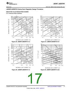
D. From the inductor value selection guide shown in Figure 29, the
inductance region intersected by the 35 (V • μs) horizontal line and
•
VD = diode forward voltage drop = 0.5V
B. Use the E • T value from the previous formula and match it with the 0.5A vertical line is 150 μH, and the inductor code is L19.
the E • T number on the vertical axis of the Inductor Value Selection
Guide shown in Figure 29.
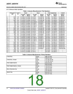
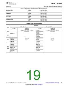
E. From Table 3, locate line L19, and select an inductor part number
from the list of manufacturers part numbers.
C. on the horizontal axis, select the maximum load current.
D. Identify the inductance region intersected by the E • T value and
the Maximum Load Current value. Each region is identified by an
inductance value and an inductor code (LXX).
E. Select an appropriate inductor from the four manufacturer's part
numbers listed in Table 3.
3. Output Capacitor Selection (COUT
)
3. Output Capacitor SeIection (COUT)
A. In the majority of applications, low ESR electrolytic or solid A. See section on OUTPUT CAPACITOR in Application Information
tantalum capacitors between 82 μF and 220 μF provide the best section.
results. This capacitor should be located close to the IC using short
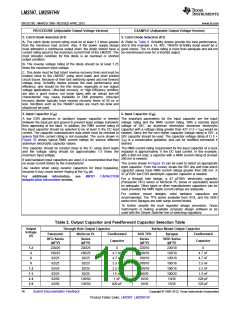
B. From the quick design table shown in Table 2, locate the output
capacitor leads and short copper traces. Do not use capacitors
voltage column. From that column, locate the output voltage closest
larger than 220 μF. For additional information, see OUTPUT
to the output voltage in your application. In this example, select the
24V line. Under OUTPUT CAPACITOR, select a capacitor from the
CAPACITOR in Application Information section.
B. To simplify the capacitor selection procedure, refer to the quick list of through hole electrolytic or surface mount tantalum types from
design table shown in Table 2. This table contains different output four different capacitor manufacturers. It is recommended that both
voltages, and lists various output capacitors that will provide the best the manufacturers and the manufacturers series that are listed in the
design solutions.
table be used.
C. The capacitor voltage rating should be at least 1.5 times greater In this example, through hole aluminum electrolytic capacitors from
than the output voltage, and often much higher voltage ratings are several different manufacturers are available.
needed to satisfy the low ESR requirements needed for low output
ripple voltage.
82 μF 50V Panasonic HFQ Series
120 μF 50V Nichicon PL Series
C. For a 20V output, a capacitor rating of at least 30V or more is
needed. In this example, either a 35V or 50V capacitor would work.
A 50V rating was chosen because it has a lower ESR which
provides a lower output ripple voltage.
Other manufacturers or other types of capacitors may also be used,
provided the capacitor specifications (especially the 100 kHz ESR)
closely match the types listed in the table. Refer to the capacitor
manufacturers data sheet for this information.
4. Feedforward Capacitor (CFF) (See Figure 31)
4. Feedforward Capacitor (CFF)
For output voltages greater than approximately 10V, an additional Table 2 contains feed forward capacitor values for various output
capacitor is required. The compensation capacitor is typically voltages. In this example, a 1 nF capacitor is needed.
between 50 pF and 10 nF, and is wired in parallel with the output
voltage setting resistor, R2. It provides additional stability for high
output voltages, low input-output voltages, and/or very low ESR
output capacitors, such as solid tantalum capacitors.
This capacitor type can be ceramic, plastic, silver mica, etc.
(Because of the unstable characteristics of ceramic capacitors made
with Z5U material, they are not recommended.)
Copyright © 1998–2013, Texas Instruments Incorporated
Submit Documentation Feedback
15
Product Folder Links: LM2597 LM2597HV

 TI [ TEXAS INSTRUMENTS ]