LM2597, LM2597HV
www.ti.com
SNVS119C –MARCH 1998–REVISED APRIL 2013
PROCEDURE (Fixed Output Voltage Version)
3. Catch Diode Selection (D1)
EXAMPLE (Fixed Output Voltage Version)
3. Catch Diode Selection (D1)
A. The catch diode current rating must be at least 1.3 times greater A. Refer to Table 6. In this example, a 1A, 20V, 1N5817 Schottky
than the maximum load current. Also, if the power supply design diode will provide the best performance, and will not be overstressed
must withstand a continuous output short, the diode should have a even for a shorted output.
current rating equal to the maximum current limit of the LM2597. The
most stressful condition for this diode is an overload or shorted
output condition.
B. The reverse voltage rating of the diode should be at least 1.25
times the maximum input voltage.
C. This diode must be fast (short reverse recovery time) and must be
located close to the LM2597 using short leads and short printed
circuit traces. Because of their fast switching speed and low forward
voltage drop, Schottky diodes provide the best performance and
efficiency, and should be the first choice, especially in low output
voltage applications. Ultra-fast recovery, or High-Efficiency rectifiers
also provide good results. Ultra-fast recovery diodes typically have
reverse recovery times of 50 ns or less. Rectifiers such as the
1N4001 series are much too slow and should not be used.
4. Input Capacitor (CIN
)
4. Input Capacitor (CIN)
A low ESR aluminum or tantalum bypass capacitor is needed The important parameters for the Input capacitor are the input
between the input pin and ground to prevent large voltage transients voltage rating and the RMS current rating. With a nominal input
from appearing at the input. In addition, the RMS current rating of voltage of 12V, an aluminum electrolytic capacitor with a voltage
the input capacitor should be selected to be at least ½ the DC load rating greater than 18V (1.5 × VIN) would be needed. The next
current. The capacitor manufacturers data sheet must be checked to higher capacitor voltage rating is 25V.
assure that this current rating is not exceeded. The curve shown in
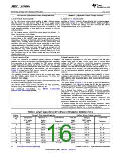
The RMS current rating requirement for the input capacitor in a buck
Figure 35 shows typical RMS current ratings for several different
regulator is approximately ½ the DC load current. In this example,
aluminum electrolytic capacitor values.
with a 400 mA load, a capacitor with a RMS current rating of at least
This capacitor should be located close to the IC using short leads 200 mA is needed. The curves shown in Figure 35 can be used to
and the voltage rating should be approximately 1.5 times the select an appropriate input capacitor. From the curves, locate the
maximum input voltage.
25V line and note which capacitor values have RMS current ratings
greater than 200 mA. Either a 47 μF or 68 μF, 25V capacitor could
be used.
If solid tantalum input capacitors are used, it is recommended that
they be surge current tested by the manufacturer.
For
a through hole design, a 68 μF/25V electrolytic capacitor
Use caution when using ceramic capacitors for input bypassing,
because it may cause severe ringing at the VIN pin.
(Panasonic HFQ series or Nichicon PL series or equivalent) would
be adequate. Other types or other manufacturers capacitors can be
used provided the RMS ripple current ratings are adequate.
For additional information, see section on INPUT CAPACITOR in
Application Information section.
For surface mount designs, solid tantalum capacitors are
recommended. The TPS series available from AVX, and the 593D
series from Sprague are both surge current tested.
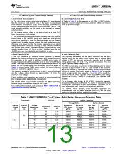
Table 1. LM2597/LM2597HV Fixed Voltage Quick Design Component Selection Table
Conditions
Inductor
Output Capacitor
Surface Mount
Through Hole
Panasonic Nichicon
HFQ Series
Voltage
Output
(V)
Current
Load
(A)
Voltage
Max Input
(V)
AVX TPS
Series
(μF/V)
Sprague
595D Series
(μF/V)
Inductance
Inductor
(#)
PL Series
(μF/V)
(μH)
(μF/V)
5
7
33
47
L14
L13
L21
L20
L4
220/16
120/25
120/25
120/35
120/25
120/16
120/16
220/16
120/25
120/25
120/35
120/25
120/16
120/16
100/16
100/16
100/16
100/16
100/16
100/16
100/16
100/6.3
100/6.3
100/6.3
100/6.3
100/6.3
100/6.3
100/6.3
0.5
0.2
10
40
6
68
3.3
100
68
10
40
150
220
L10
L9
Copyright © 1998–2013, Texas Instruments Incorporated
Submit Documentation Feedback
13
Product Folder Links: LM2597 LM2597HV

 TI [ TEXAS INSTRUMENTS ]