LM2596
SNVS124C –NOVEMBER 1999–REVISED APRIL 2013
www.ti.com
APPLICATION INFORMATION
Table 7. PIN DESCRIPTIONS
Name
+VIN
Description
This is the positive input supply for the IC switching regulator. A suitable input bypass
capacitor must be present at this pin to minimize voltage transients and to supply the
switching currents needed by the regulator.
Ground
Output
Feedback
Circuit ground.
Internal switch. The voltage at this pin switches between (+VIN − VSAT) and approximately
−0.5V, with a duty cycle of approximately VOUT/VIN. To minimize coupling to sensitive
circuitry, the PC board copper area connected to this pin should be kept to a minimum.
Senses the regulated output voltage to complete the feedback loop.
Allows the switching regulator circuit to be shut down using logic level signals thus dropping
the total input supply current to approximately 80 μA. Pulling this pin below a threshold
voltage of approximately 1.3V turns the regulator on, and pulling this pin above 1.3V (up to a
maximum of 25V) shuts the regulator down. If this shutdown feature is not needed, the ON
/OFF pin can be wired to the ground pin or it can be left open, in either case the regulator will
be in the ON condition.
ON /OFF
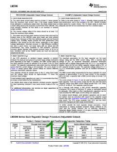
EXTERNAL COMPONENTS
INPUT CAPACITOR
CIN — A low ESR aluminum or tantalum bypass capacitor is needed between the input pin and ground pin. It
must be located near the regulator using short leads. This capacitor prevents large voltage transients from
appearing at the input, and provides the instantaneous current needed each time the switch turns on.
The important parameters for the Input capacitor are the voltage rating and the RMS current rating. Because of
the relatively high RMS currents flowing in a buck regulator's input capacitor, this capacitor should be chosen for
its RMS current rating rather than its capacitance or voltage ratings, although the capacitance value and voltage
rating are directly related to the RMS current rating.
The RMS current rating of a capacitor could be viewed as a capacitor's power rating. The RMS current flowing
through the capacitors internal ESR produces power which causes the internal temperature of the capacitor to
rise. The RMS current rating of a capacitor is determined by the amount of current required to raise the internal
temperature approximately 10°C above an ambient temperature of 105°C. The ability of the capacitor to dissipate
this heat to the surrounding air will determine the amount of current the capacitor can safely sustain. Capacitors
that are physically large and have a large surface area will typically have higher RMS current ratings. For a given
capacitor value, a higher voltage electrolytic capacitor will be physically larger than a lower voltage capacitor, and
thus be able to dissipate more heat to the surrounding air, and therefore will have a higher RMS current rating.
The consequences of operating an electrolytic capacitor above the RMS current rating is a shortened operating
life. The higher temperature speeds up the evaporation of the capacitor's electrolyte, resulting in eventual failure.
Selecting an input capacitor requires consulting the manufacturers data sheet for maximum allowable RMS ripple
current. For a maximum ambient temperature of 40°C, a general guideline would be to select a capacitor with a
ripple current rating of approximately 50% of the DC load current. For ambient temperatures up to 70°C, a
current rating of 75% of the DC load current would be a good choice for a conservative design. The capacitor
voltage rating must be at least 1.25 times greater than the maximum input voltage, and often a much higher
voltage capacitor is needed to satisfy the RMS current requirements.
A graph shown in Figure 25 shows the relationship between an electrolytic capacitor value, its voltage rating, and
the RMS current it is rated for. These curves were obtained from the Nichicon “PL” series of low ESR, high
reliability electrolytic capacitors designed for switching regulator applications. Other capacitor manufacturers offer
similar types of capacitors, but always check the capacitor data sheet.
“Standard” electrolytic capacitors typically have much higher ESR numbers, lower RMS current ratings and
typically have a shorter operating lifetime.
18
Submit Documentation Feedback
Copyright © 1999–2013, Texas Instruments Incorporated
Product Folder Links: LM2596

 TI [ TEXAS INSTRUMENTS ]