LM2596
www.ti.com
SNVS124C –NOVEMBER 1999–REVISED APRIL 2013
In many cases the preferred mode of operation is the continuous mode. It offers greater output power, lower
peak switch, inductor and diode currents, and can have lower output ripple voltage. But it does require larger
inductor values to keep the inductor current flowing continuously, especially at low output load currents and/or
high input voltages.
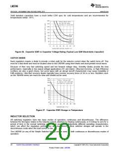
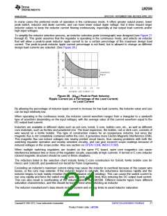
To simplify the inductor selection process, an inductor selection guide (nomograph) was designed (see Figure 21
through 8). This guide assumes that the regulator is operating in the continuous mode, and selects an inductor
that will allow a peak-to-peak inductor ripple current to be a certain percentage of the maximum design load
current. This peak-to-peak inductor ripple current percentage is not fixed, but is allowed to change as different
design load currents are selected. (See Figure 28.)
Figure 28. (ΔIIND) Peak-to-Peak Inductor
Ripple Current (as a Percentage of the Load Current)
vs Load Current
By allowing the percentage of inductor ripple current to increase for low load currents, the inductor value and size
can be kept relatively low.
When operating in the continuous mode, the inductor current waveform ranges from a triangular to a sawtooth
type of waveform (depending on the input voltage), with the average value of this current waveform equal to the
DC output load current.
Inductors are available in different styles such as pot core, toroid, E-core, bobbin core, etc., as well as different
core materials, such as ferrites and powdered iron. The least expensive, the bobbin, rod or stick core, consists of
wire wound on a ferrite bobbin. This type of construction makes for an inexpensive inductor, but since the
magnetic flux is not completely contained within the core, it generates more Electro-Magnetic Interference (EMl).
This magnetic flux can induce voltages into nearby printed circuit traces, thus causing problems with both the
switching regulator operation and nearby sensitive circuitry, and can give incorrect scope readings because of
induced voltages in the scope probe. Also see section on OPEN CORE INDUCTORS.
When multiple switching regulators are located on the same PC board, open core magnetics can cause
interference between two or more of the regulator circuits, especially at high currents. A torroid or E-core inductor
(closed magnetic structure) should be used in these situations.
The inductors listed in the selection chart include ferrite E-core construction for Schott, ferrite bobbin core for
Renco and Coilcraft, and powdered iron toroid for Pulse Engineering.
Exceeding an inductor's maximum current rating may cause the inductor to overheat because of the copper wire
losses, or the core may saturate. If the inductor begins to saturate, the inductance decreases rapidly and the
inductor begins to look mainly resistive (the DC resistance of the winding). This can cause the switch current to
rise very rapidly and force the switch into a cycle-by-cycle current limit, thus reducing the DC output load current.
This can also result in overheating of the inductor and/or the LM2596. Different inductor types have different
saturation characteristics, and this should be kept in mind when selecting an inductor.
The inductor manufacturer's data sheets include current and energy limits to avoid inductor saturation.
Copyright © 1999–2013, Texas Instruments Incorporated
Submit Documentation Feedback
21
Product Folder Links: LM2596

 TI [ TEXAS INSTRUMENTS ]