LM2596
SNVS124C –NOVEMBER 1999–REVISED APRIL 2013
www.ti.com
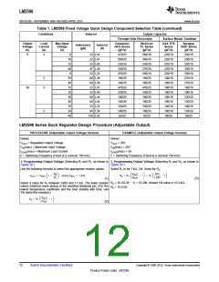
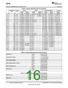
Table 1. LM2596 Fixed Voltage Quick Design Component Selection Table (continued)
Conditions
Inductor
Output Capacitor
Through Hole Electrolytic Surface Mount Tantalum
Output
Voltage
(V)
Load
Current
(A)
Max Input
Voltage
(V)
Panasonic
HFQ Series
(μF/V)
Nichicon
PL Series
(μF/V)
AVX TPS
Series
(μF/V)
Sprague
595D Series
(μF/V)
Inductance
(μH)
Inductor
(#)
5
3
8
22 L41
470/25
560/25
330/35
330/35
470/25
180/35
180/35
470/25
330/25
180/25
180/35
330/25
180/25
82/25
560/16
560/25
330/35
270/35
560/16
180/35
180/35
470/25
330/25
180/25
180/35
330/25
180/25
82/25
220/10
220/10
220/10
220/10
220/10
100/10
100/10
100/16
100/16
100/16
100/16
100/16
100/16
68/20
330/10
330/10
330/10
330/10
330/10
270/10
270/10
180/16
180/16
120/20
120/20
180/16
120/20
68/25
10
15
40
9
22 L41
33 L40
47 L39
22 L33
68 L38
68 L38
22 L41
33 L40
68 L44
68 L44
33 L32
68 L38
150 L42
2
3
20
40
15
18
30
40
15
20
40
12
2
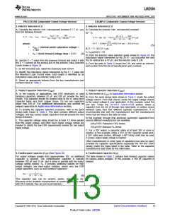
LM2596 Series Buck Regulator Design Procedure (Adjustable Output)
PROCEDURE (Adjustable Output Voltage Version)
EXAMPLE (Adjustable Output Voltage Version)
Given:
Given:
VOUT = Regulated Output Voltage
VOUT = 20V
VIN(max) = Maximum Input Voltage
VIN(max) = 28V
ILOAD(max) = Maximum Load Current
F = Switching Frequency (Fixed at a nominal 150 kHz).
ILOAD(max) = 3A
F = Switching Frequency (Fixed at a nominal 150 kHz).
1. Programming Output Voltage (Selecting R1 and R2, as shown in 1. Programming Output Voltage (Selecting R1 and R2, as shown in
Figure 20 )
Figure 20 )
Use the following formula to select the appropriate resistor values.
Select R1 to be 1 kΩ, 1%. Solve for R2.
(3)
(1)
R2 = 1k (16.26 − 1) = 15.26k, closest 1% value is 15.4 kΩ.
R2 = 15.4 kΩ.
Select a value for R1 between 240Ω and 1.5 kΩ. The lower resistor
values minimize noise pickup in the sensitive feedback pin. (For the
lowest temperature coefficient and the best stability with time, use
1% metal film resistors.)
(2)
12
Submit Documentation Feedback
Copyright © 1999–2013, Texas Instruments Incorporated
Product Folder Links: LM2596

 TI [ TEXAS INSTRUMENTS ]