LM2596
www.ti.com
SNVS124C –NOVEMBER 1999–REVISED APRIL 2013
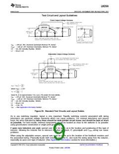
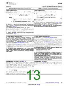
Test Circuit and Layout Guidelines
Fixed Output Voltage Versions
CIN —470 μF, 50V, Aluminum Electrolytic Nichicon “PL Series”
COUT —220 μF, 25V Aluminum Electrolytic, Nichicon “PL Series”
D1 —5A, 40V Schottky Rectifier, 1N5825
L1 —68 μH, L38
Adjustable Output Voltage Versions
where VREF = 1.23V
Select R1 to be approximately 1 kΩ, use a 1% resistor for best stability.
CIN —470 μF, 50V, Aluminum Electrolytic Nichicon “PL Series”
COUT —220 μF, 35V Aluminum Electrolytic, Nichicon “PL Series”
D1 —5A, 40V Schottky Rectifier, 1N5825
L1 —68 μH, L38
R1 —1 kΩ, 1%
CFF —See Application Information Section
Figure 20. Standard Test Circuits and Layout Guides
As in any switching regulator, layout is very important. Rapidly switching currents associated with wiring
inductance can generate voltage transients which can cause problems. For minimal inductance and ground
loops, the wires indicated by heavy lines should be wide printed circuit traces and should be kept as short
as possible. For best results, external components should be located as close to the switcher lC as possible
using ground plane construction or single point grounding.
If open core inductors are used, special care must be taken as to the location and positioning of this type of
inductor. Allowing the inductor flux to intersect sensitive feedback, lC groundpath and COUT wiring can cause
problems.
When using the adjustable version, special care must be taken as to the location of the feedback resistors and
the associated wiring. Physically locate both resistors near the IC, and route the wiring away from the inductor,
especially an open core type of inductor. (See Application Information section for more information.)
Copyright © 1999–2013, Texas Instruments Incorporated
Submit Documentation Feedback
9
Product Folder Links: LM2596

 TI [ TEXAS INSTRUMENTS ]