LF155, LF156, LF355, LF356, LF357
www.ti.com
SNOSBH0C –MAY 2000–REVISED MARCH 2013
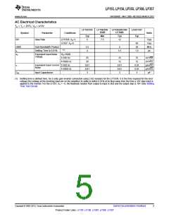
AC Electrical Characteristics
TA = TJ = 25°C, VS = ±15V
LF155/355
LF156/256/
356B
LF156/256/356/
LF356B
LF257/357
Typ
Symbol
Parameter
Slew Rate
Conditions
Units
Typ
Min
Typ
SR
LF155/6: AV=1,
LF357: AV=5
5
7.5
12
V/μs
V/μs
MHz
μs
50
20
GBW
ts
Gain Bandwidth Product
Settling Time to 0.01%
2.5
4
5
(1)
1.5
1.5
en
Equivalent Input Noise
Voltage
RS=100Ω
f=100 Hz
f=1000 Hz
25
20
15
12
15
12
nV/√Hz
nV/√Hz
pA/√Hz
pA/√Hz
pF
in
Equivalent Input Current f=100 Hz
0.01
0.01
3
0.01
0.01
3
0.01
0.01
3
Noise
f=1000 Hz
CIN
Input Capacitance
(1) Settling time is defined here, for a unity gain inverter connection using 2 kΩ resistors for the LF155/6. It is the time required for the error
voltage (the voltage at the inverting input pin on the amplifier) to settle to within 0.01% of its final value from the time a 10V step input is
applied to the inverter. For the LF357, AV = −5, the feedback resistor from output to input is 2kΩ and the output step is 10V (See Settling
Time Test Circuit).
Copyright © 2000–2013, Texas Instruments Incorporated
Submit Documentation Feedback
5
Product Folder Links: LF155 LF156 LF355 LF356 LF357

 TI [ TEXAS INSTRUMENTS ]