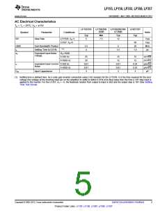
LF155, LF156, LF355, LF356, LF357
www.ti.com
SNOSBH0C –MAY 2000–REVISED MARCH 2013
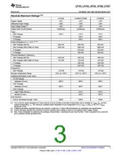
Absolute Maximum Ratings(1)(2)
LF155/6
±22V
LF256/7/LF356B
±22V
LF355/6/7
±18V
Supply Voltage
Differential Input Voltage
±40V
±40V
±30V
(3)
Input Voltage Range
±20V
±20V
±16V
Output Short Circuit Duration
TJMAX
Continuous
Continuous
Continuous
LMC Package
P Package
150°C
115°C
100°C
100°C
115°C
100°C
100°C
D Package
(1) (4)
Power Dissipation at TA = 25°C
LMC Package (Still Air)
LMC Package (400 LF/Min Air Flow)
P Package
560 mW
400 mW
1000 mW
670 mW
380 mW
400 mW
1000 mW
670 mW
380 mW
1200 mW
D Package
Thermal Resistance (Typical) θJA
LMC Package (Still Air)
LMC Package (400 LF/Min Air Flow)
P Package
160°C/W
65°C/W
160°C/W
65°C/W
160°C/W
65°C/W
130°C/W
195°C/W
130°C/W
195°C/W
D Package
(Typical) θJC
LMC Package
23°C/W
23°C/W
23°C/W
Storage Temperature Range
Soldering Information (Lead Temp.)
TO-99 Package
−65°C to +150°C
−65°C to +150°C
−65°C to +150°C
Soldering (10 sec.)
300°C
260°C
300°C
260°C
300°C
260°C
PDIP Package
Soldering (10 sec.)
SOIC Package
Vapor Phase (60 sec.)
Infrared (15 sec.)
215°C
220°C
215°C
220°C
ESD tolerance
(100 pF discharged through 1.5kΩ)
1000V
1000V
1000V
(1) The maximum power dissipation for these devices must be derated at elevated temperatures and is dictated by TJMAX, θJA, and the
ambient temperature, TA. The maximum available power dissipation at any temperature is PD=(TJMAX−TA)/θJA or the 25°C PdMAX
whichever is less.
,
(2) If Military/Aerospace specified devices are required, contact the TI Sales Office/Distributors for availability and specifications.
(3) Unless otherwise specified the absolute maximum negative input voltage is equal to the negative power supply voltage.
(4) Max. Power Dissipation is defined by the package characteristics. Operating the part near the Max. Power Dissipation may cause the
part to operate outside specified limits.
Copyright © 2000–2013, Texas Instruments Incorporated
Submit Documentation Feedback
3
Product Folder Links: LF155 LF156 LF355 LF356 LF357

 TI [ TEXAS INSTRUMENTS ]