ISO1540
ISO1541
SLLSEB6 –JULY 2012
www.ti.com
DEVICE INFORMATION
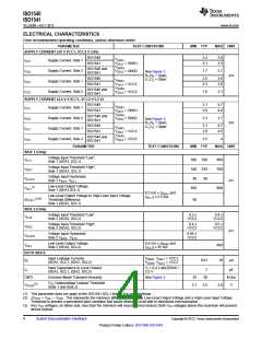
Table 2. IEC INSULATION AND SAFETY-RELATED SPECIFICATION FOR D-8 PACKAGE
Over recommended operating conditions, unless otherwise noted
PARAMETER
TEST CONDITIONS
MIN
TYP
MAX
UNIT
Shortest terminal-to-terminal distance
through air
L(I01)
L(I02)
CTI
Minimum air gap (Clearance)
4.8
mm
Minimum external tracking
(Creepage)
Shortest terminal-to-terminal distance
across the package surface
4.3
>400
0.014
mm
V
Tracking resistance (comparative
tracking index)
DIN IEC 60112 / VDE 0303 Part 1
Distance through the insulation
Minimum internal gap (internal
clearance)
mm
VIO = 500 V, TA < 100°C
>1012
>1011
Ω
Ω
Isolation resistance, input to
output(1)
RIO
VIO = 500 V, 100°C ≤ TA
Barrier capacitance, input to
output(1)
Input capacitance(2)
CIO
CI
VIO = 0.4 x sin(2E6πt)
1
pF
pF
See Electrical Characteristics
(1) All pins on each side of the barrier tied together creating a two-terminal device.
(2) Measured from input pin to ground.
spacer
NOTE
Creepage and clearance requirements should be applied according to the specific
application isolation standards. Care should be taken to maintain these distances on a
board design to ensure that the mounting pads for the isolator do not reduce this distance.
Creepage and clearance on the printed-circuit board become equal in certain cases.
Techniques such as inserting grooves and/or ribs on the printed circuit board are used to
help increase these specifications.
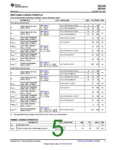
Table 3. IEC 60747-5-2 INSULATION CHARACTERISTICS(1)
Over recommended operating conditions, unless otherwise noted
PARAMETER
TEST CONDITIONS
SPECIFICATION
UNIT
VPEAK
Ω
Maximum working insulation
voltage
VIORM
566
Method a, After environmental tests subgroup 1,
VPR = VIORM x 1.6, t = 10 sec,
Partial Discharge < 5 pC
906
1062
680
Method b1, After environmental tests subgroup 1,
VPR = VIORM x 1.875, t = 1 sec (100% production),
Partial Discharge < 5 pC
Input-to-Output test voltage per IEC
60747-5-2
VPR
After Input/Output safety test subgroup 2/3,
VPR = VIORM x 1.2, t = 10 sec,
Partial Discharge < 5 pC
VTEST = VOITM
t = 60 sec (qualification)
t = 1 sec (100% production)
Transient overvoltage per IEC
60747-5-2
VIOTM
RS
4000
Insulation resistance
Pollution degree
VIO = 500 V at TS
>109
2
(1) Climatic Classification 40/125/21
8
Submit Documentation Feedback
Copyright © 2012, Texas Instruments Incorporated
Product Folder Link(s): ISO1540 ISO1541

 TI [ TEXAS INSTRUMENTS ]