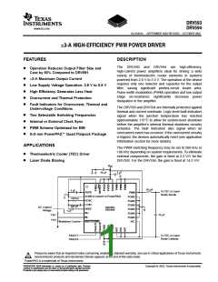
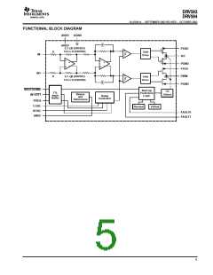
DRV593
DRV594
www.ti.com
SLOS401A - SEPTEMBER 2002 REVISED - OCTOBER 2002
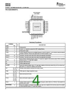
PIN ASSIGNMENTS
VFP PACKAGE
(TOP VIEW)
32 31 30 29 28 27 26 25
1
2
3
4
5
6
7
8
AVDD
AGND
ROSC
PWM
24
23
PGND
22 PGND
21
20
19
18
17
COSC
AREF
PGND
PGND
PGND
PGND
H/C
PowerPAD
IN+
IN-
SHUTDOWN
9 10 11 12 13 14 15 16
Terminal Functions
TERMINAL
I/O
DESCRIPTION
NAME
AGND
NO.
2
Analog ground
AREF
AVDD
COSC
5
1
4
O
I
Connect 1 µF capacitor to ground for AREF voltage filtering
Analog power supply
I
Connect capacitor to ground to set oscillation frequency (220 pF for 500 kHz, 1 nF for 100 kHz) when the internal
oscillator is selected; connect clock signal when an external oscillator is used
FAULT0
FAULT1
10
9
O
O
Fault flag 0, low when active open drain output (see application information)
Fault flag 1, low when active open drain output (see application information)
Selects 500 kHz switching frequency when a TTL logic low is applied to this terminal; selects 100 kHz switching
frequency when a TTL logic high is applied
FREQ
IN-
32
7
I
I
I
I
Negative differential input
Positive differential input
IN+
6
INT/EXT
31
Selects the internal oscillator when a TTL logic high is applied to this terminal; selects the use of an external oscil-
lator when a TTL logic low is applied to this terminal
H/C
14, 15,
16, 17
O
O
Direction control output for heat and cool modes (4 pins)
PWM output for voltage magnitude (4 pins)
High-current ground (6 pins)
PWM
PGND
24, 25,
26, 27
18, 19,
20, 21,
22, 23
PVDD
11, 12,
13, 28,
29, 30
I
High-current power supply (6 pins)
ROSC
3
I
I
Connect 120-kΩ resistor to AGND to set oscillation frequency (either 500 kHz or 100 kHz). Not needed if an
external clock is used.
SHUTDOWN
8
Places the amplifier in shutdown mode when a TTL logic low is applied to this terminal; places the amplifier
in normal operation when a TTL logic high is applied
4

 TI [ TEXAS INSTRUMENTS ]