www.ti.com
ꢀ ꢁꢂ ꢃꢄ ꢅ
SLOS390A – NOVEMBER 2001– REVISED MAY 2002
APPLICATION INFORMATION
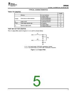
L
DRIVING EXTERNALLY-GENERATED PWM
TO THE DRV592 INPUTS
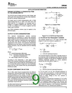
OUT+
C
C
R
TEC
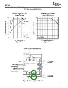
The DRV592 may be simply viewed as a full-H-bridge, with
all the gate drive and protection circuitry fully integrated,
but with no internal PWM generator.
L
OUT–
The inputs may be driven independently with a PWM
signal ranging from dc to 1 MHz. The HIGH and LOW
levels must be TTL compatible. For example, when a
voltage 2 V or higher is applied to IN+, then OUT+ goes
to VDD. If a voltage 0.8 V or lower is applied, then the
output goes to ground.
Figure 13. LC Output Filter
L
OUT+
or
OUT–
Any PWM modulation scheme may be applied to the
DRV592 inputs.
C
TEC
R
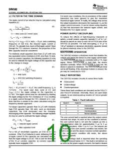
OUTPUT FILTER CONSIDERATIONS
Figure 14. LC Half-Circuit Equivalent
TEC element manufacturers provide electrical
specifications for maximum dc current and maximum
output voltage for each particular element. The maximum
ripple current, however, is typically only recommended to
be less than 10% with no reference to the frequency
components of the current. The maximum temperature
differential across the element, which decreases as ripple
current increases, may be calculated with the following
equation:
LC FILTER IN THE FREQUENCY DOMAIN
nd
The transfer function for a 2
order low-pass filter
(Figures 13 and 14) is shown in equation (2):
1
(2)
H
(jw) +
LP
2
jw
w
–ǒ Ǔ
w
1
Q
)
) 1
w
0
0
1
(1)
1
DT +
DT
max
w
+
2
ǒ
Ǔ
0
1 ) N
Ǹ
LC
Q + quality factor
w + DRV592 switching frequency
Where:
∆T = actual temperature differential
∆T
= maximum temperature differential
(specified by manufacturer)
max
The resonant frequency for the filter is typically chosen to
be at least one order of magnitude lower than the switching
frequency. Equation (2) may then be simplified to give the
following magnitude equation (3). These equations
assume the use of the filter in Figure 13.
N = ratio of ripple current to dc current
According to this relationship, a 10% ripple current
reduces the maximum temperature differential by 1%. An
LC network may be used to filter the current flowing to the
TEC to reduce the amount of ripple and, more importantly,
protect the rest of the system from any electromagnetic
interference (EMI).
(3)
f
s
ŤHLPŤdB
+ –40 log ǒ Ǔ
Ǹ
f
o
1
f
+
o
2p LC
FILTER COMPONENT SELECTION
f + 500 kHz (DRV592 switching frequency)
s
If L=10 µH and C=10 µF, the resonant frequency is
15.9 kHz, which corresponds to –60 dB of attenuation at
the 500 kHz switching frequency. For VDD = 5 V, the
amount of ripple voltage at the TEC element is
approximately 5 mV.
The LC filter, which may be designed from two different
perspectives, both described below, will help estimate the
overall performance of the system. The filter should be
designed for the worst-case conditions during operation,
which is typically when the differential output is at 50% duty
cycle. The following section serves as a starting point for
the design, and any calculations should be confirmed with
a prototype circuit in the lab.
The average TEC element has a resistance of 1.5 Ω, so the
ripple current through the TEC is approximately 3.4 mA. At
the 3-A maximum output current of the DRV592, this
3.4 mA corresponds to 0.011% ripple current, causing less
than 0.0001% reduction of the maximum temperature
differential of the TEC element (see equation 1).
Any filter should always be placed as close as possible to
the DRV592 to reduce EMI.
9

 TI [ TEXAS INSTRUMENTS ]