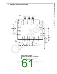
6.0 Hardware User Information (Continued)
Symptoms:
the DP83840A will be half it’s normal amplitude. This
indicates that the 10 Mb/s section of the chip has not
powered up properly.
National believes that there will be no system ramification
due to the DP83840A not meeting the IEEE specification
for return loss. National Semiconductor has done extensive Solution/Workaround:
system testing with DP83840A’s that have return loss in
the range of 4-6dB, and did not see any degradation in
system performance.
It is recommended that in 10/100 application that the low
power mode of the device not be used.
In 100 Mb/s only applications, it is recommended that the
low power pin be pulled high through a 4.7kΩ resister.
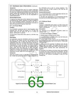
Solution/Workaround:
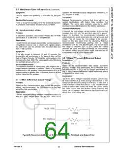
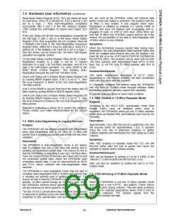
To improve the return loss at idle, National Semiconductor
recommends that 1000pF capacitors be place in parallel to
the 10.5Ω termination resistors connected to the TXU+/-
pins. Figure 26 illustrates the recommended connection of
external components to improve return loss.
6.10 Software Reset
Problem:
Hardware Configuration pins require a (4.7kΩ or less) pull
up/down resistor to insure that the Physical Address is
stable at latching time.
6.9 Low Power Mode
Problem:
Description:
The DP83840A sometimes fails to Auto-Negotiate when
switching from 100 Mb/s link partner to a 10 Mb/s link
partner when the low power pin (pin 2) is driven by
Speed_100/PhyAdr<3> (pin 89).
The following is an explanation of events based on
software reset:
1. First high byte is written via MDIO
The low power mode works when used in a 100 Mb/s only
operation.
2. Software reset is true for the next 500ns.
3. At synchronous de-assertion of the reset all mode pins
and Phy Address pins are latched.
Description:
Any application using the DP83840A (with the low power
pin driven by the Speed_100 pin) will sometimes fail to
Auto-Negotiate to the 10 Mb/s link partner that has first
established a link with a 100 Mb/s link partner and then is
4. Output enables for Phy Address pins are disabled (they
will become inputs) from start of the reset to 1700ns after
reset assertion.
disconnected from the 100 Mb/s link partner and then 5. Within 250ns from assertion of software reset, the phy
connected to a 10 Mb/s link partner. The reason for this is address has to be stable. This implies that the RC time
that in 100 Mb/s mode, the part will be configured for low constant should be faster than 250ns so that Phy address
power mode and shut down the 10 Mb/s and Auto- will be latched correctly with reset synchronous de-
Negotiation circuitry in the DP83840A and when it tries to assertion.
connect to a 10 Mb/s link partner the 10 Mb/s and Auto-
Negotiation circuitry might not be fully powered up.
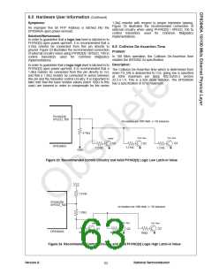
6. DP83840A Phy Address pin drivers have been modified
to provide more drive current than the DP83840. This will
Symptoms:
increase the capacitance at the pin, hence the resistance
will need to be reduced accordingly to keep the time
constant low.
When this problem occurs, no link will be established with
the 10 Mb/s link partner and the FLP signal being sent by
1000pF
1:2
Pin 25 (TXU-)
2
10.5Ω
10.5Ω
Pin 24 (TXU+)
DP83840A
1
RJ45
1000pF
Figure 26. Recommended External Circuitry to Improve Transmit Return Loss
Version A
National Semiconductor
64

 TI [ TEXAS INSTRUMENTS ]