DM385, DM388
SPRS821D –MARCH 2013–REVISED DECEMBER 2013
www.ti.com
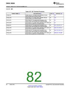
3.3.12 I2C
Table 3-27. I2C Terminal Functions
SIGNAL NAME [1]
DESCRIPTION [2]
TYPE [3]
AAR BALL [4]
I2C[0]_SCL
I2C[0]_SDA
I2C[1]_SCL
I2C[1]_SDA
I2C[2]_SCL
I2C[2]_SDA
I2C[3]_SCL
I2C[3]_SDA
I2C[0] Clock I/O. For proper device operation, this pin
must be pulled up via external resistor.
I/O
T27
T24
D2
I2C[0] Data I/O. For proper device operation, this pin
must be pulled up via external resistor.
I/O
I/O
I2C[1] Clock I/O. For proper device operation in I2C
mode, this pin must be pulled up via external resistor.
I2C[1] Data I/O. For proper device operation in I2C mode, I/O
this pin must be pulled up via external resistor.
D1
I2C[2] Clock I/O. For proper device operation in I2C
mode, this pin must be pulled up via external resistor.
I/O
E31, J13, K11, L2
AG4, C12, E29, L4
AE31, G3, K10, L22
AE30, D7, H5, M21
I2C[2] Data I/O. For proper device operation in I2C mode, I/O
this pin must be pulled up via external resistor.
I2C[3] Clock I/O. For proper device operation in I2C
mode, this pin must be pulled up via external resistor.
I/O
I2C[3] Data I/O. For proper device operation in I2C mode, I/O
this pin must be pulled up via external resistor.
82
Device Pins
Copyright © 2013, Texas Instruments Incorporated
Submit Documentation Feedback
Product Folder Links: DM385 DM388

 TI [ TEXAS INSTRUMENTS ]