DM385, DM388
www.ti.com
SPRS821D –MARCH 2013–REVISED DECEMBER 2013
7.3 Reset
7.3.1 System-Level Reset Sources
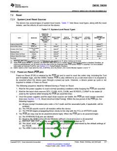
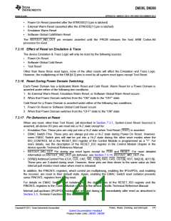
The device has several types of system-level resets. Table 7-7 lists these reset types, along with the reset
initiator, and the effects of each reset on the device.
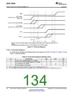
Table 7-7. System-Level Reset Types
RESETS ALL
MODULES,
EXCLUDING EMAC
SWITCH,
EMULATION, PLL
AND CLOCK
CONFIG
ASSERTS
RSTOUT_WD_OUT
PIN
RESETS EMAC
SWITCH
RESETS
EMULATION
PLL AND CLOCK
CONFIG
LATCHES
BOOT PINS
TYPE
INITIATOR
Power-on Reset (POR)
External Warm Reset
POR pin
Yes
Yes
Yes
Yes
No
Yes
No
Yes
Yes
Optional(1)(2)
Optional(1)(2)
RESET pin
Optional(3)
On-Chip Emulation
Logic
Emulation Warm Reset
Yes
Optional(3)
No
No
No
Optional(1)
Watchdog Reset
Watchdog Timer
Software
Yes
Yes
Yes
No
Optional(3)
Optional(3)
Optional(3)
No
No
Yes
No
No
Yes
No
No
No
No
No
Yes
Optional(1)
Optional(1)
No
Software Global Cold Reset
Software Global Warm Reset
Test Reset
Software
TRST pin
Yes
No
(1) RSTOUT_WD_OUT pin asserted only if BTMODE[11] was latched as "0" when coming out of reset.
(2) While POR and/or RESET is asserted, the RSTOUT_WD_OUT pin is 3-stated and the internal pull resistor is disabled; therefore, an
external pullup/pulldown can be used to set the state of this pin (high/low) while POR and/or RESET is asserted. For more detailed
information on external PUs/PDs, see Section 4.5.1, Pullup/Pulldown Resistors.
(3) EMAC Switch is NOT reset when the ISO_CONTROL bit in the RESET_ISO Control Module register is set to "1".
7.3.2 Power-on Reset (POR pin)
Power-on Reset (POR) is initiated by the POR pin and is used to reset the entire chip, including the Test
and Emulation logic, and the EMAC Switch. POR is also referred to as a cold reset since it is required to
be asserted when the device goes through a power-up cycle. However, a device power-up cycle is not
required to initiate a Power-on Reset.
The following sequence must be followed during a Power-on Reset:
1. Wait for the power supplies to reach normal operating conditions while keeping the POR pin asserted.
2. Wait for the input clock sources DEV_CLKIN, AUX_CLKIN, and SERDES_CLKN/P to be stable (if
used by the system) while keeping the POR pin asserted (low).
3. Once the power supplies and the input clock sources are stable, the POR pin must remain asserted
(low) [see Section 7.3.18, Reset Electrical Data/Timing]. Within the low period of the POR pin, the
following happens:
(a) All pins except Emulation pins enter a Hi-Z mode and the associated pulls, if applicable, will be
enabled.
(b) The PRCM asserts reset to all modules within the device.
(c) The PRCM begins propagating these clocks to the chip with the PLLs in BYPASS mode.
4. The POR pin may now be de-asserted (driven high). When the POR pin is de-asserted (high):
(a) The BTMODE[15:0] pins are latched.
(b) Reset to the ARM Cortex-A8 and Modules without a local processor is de-asserted.
(c) RSTOUT_WD_OUT is briefly asserted if BTMODE[11] was latched as "0".
(d) The clock, reset, and power-down state of each peripheral is determined by the default settings of
the PRCM.
(e) The ARM Cortex-A8 begins executing from the Boot ROM.
Copyright © 2013, Texas Instruments Incorporated
Power, Reset, Clocking, and Interrupts
137
Submit Documentation Feedback
Product Folder Links: DM385 DM388

 TI [ TEXAS INSTRUMENTS ]