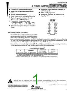
CD74HC138-Q1
HIGH-SPEED CMOS LOGIC
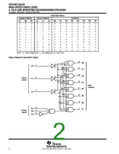
3- TO 8-LINE INVERTING DECODER/DEMULTIPLEXER
SCLS580A − APRIL 2004 − REVISED APRIL 2008
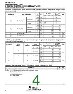
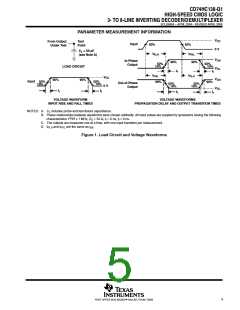
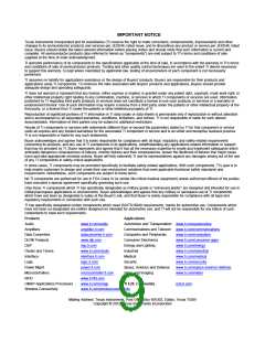
PARAMETER MEASUREMENT INFORMATION
V
CC
From Output
Under Test
Test
Point
Input
50%
50%
0 V
C = 50 pF
(see Note A)
L
t
t
PHL
PLH
V
V
OH
In-Phase
Output
90%
t
90%
50%
10%
50%
10%
LOAD CIRCUIT
OL
t
r
f
f
t
t
PLH
PHL
V
CC
V
V
OH
90%
t
90%
Input
50%
10%
50%
10%
90%
90%
t
Out-of-Phase
Output
50%
10%
50%
10%
0 V
OL
t
r
f
t
r
VOLTAGE WAVEFORM
INPUT RISE AND FALL TIMES
VOLTAGE WAVEFORMS
PROPAGATION DELAY AND OUTPUT TRANSITION TIMES
NOTES: A. C includes probe and test-fixture capacitance.
L
B. Phase relationships between waveforms were chosen arbitrarily. All input pulses are supplied by generators having the following
characteristics: PRR ≤ 1 MHz, Z = 50 Ω, t = 6 ns, t = 6 ns.
O
r
f
C. The outputs are measured one at a time, with one input transition per measurement.
D. and t are the same as t
t
.
pd
PLH
PHL
Figure 1. Load Circuit and Voltage Waveforms
5
POST OFFICE BOX 655303 • DALLAS, TEXAS 75265

 TI [ TEXAS INSTRUMENTS ]