CD4541B
Digital Timer Application
0
10
20 30 40 50
60
70 80 88
82
80
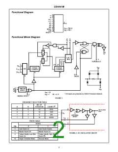
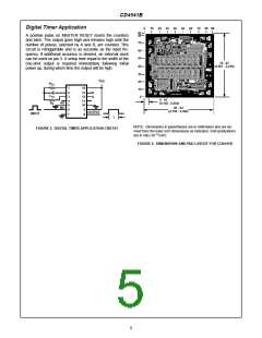
A positive pulse on MASTER RESET resets the counters
and latch. The output goes high and remains high until the
number of pulses, selected by A and B, are counted. This
circuit is retriggerable and is as accurate as the input fre-
quency. If additional accuracy is desired, an external clock
can be used on pin 3. A setup time equal to the width of the
one-shot output is required immediately following initial
power up, during which time the output will be high.
70
60
50
79 - 87
(2.007 - 2.210)
40
30
20
V
DD
R
C
TC
1
14
10
0
2
3
4
5
13
12
11
10
B
A
TC
4 - 10
(0.102 - 0.254)
R
AR
MR
S
85 - 93
6
7
9
8
(2.159 - 2.362)
OUTPUT
INPUT
t
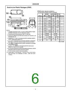
NOTE: Dimensions in parentheses are in millimeters and are de-
rived from the basic inch dimensions as indicated. Grid graduations
are in mils (10 inch).
FIGURE 3. DIGITAL TIMER APPLICATION CIRCUIT
-3
FIGURE 4. DIMENSIONS AND PAD LAYOUT FOR CD4541B
5

 TI [ TEXAS INSTRUMENTS ]