CC2510Fx / CC2511Fx
11.4.3 Hardware Breakpoints
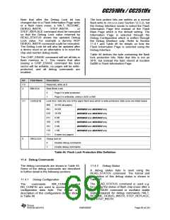
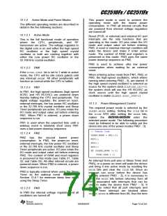
Bit Description
7:5 Unused
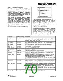
The debug command SET_HW_BRKPNT is
used to set a hardware breakpoint. The
CC2510Fx/CC2511Fx supports up to four
hardware breakpoints. When a hardware
breakpoint is enabled it will compare the CPU
address bus with the breakpoint. When a
match occurs, the CPU is halted.
4:3 Breakpoint number; 0 - 3
2
Breakpoint enable
0
1
Disable
Enable
1:0 Reserved. Must be 00.
When issuing the SET_HW_BRKPNT debug
command, the external host must supply three
data bytes that define the hardware
breakpoint. The hardware breakpoint itself
consists of 18 bits while three bits are used for
control purposes. The format of the three data
bytes for the SET_HW_BRKPNT command is
as follows.
The second data byte consists of bits 15 - 8 of
the hardware breakpoint while the third data
byte consists of bits 7 - 0 of the hardware
breakpoint. This means that the second and
third data byte sets the CPU CODE address
where the CPU is halted.
The first data byte consists of the following:
11.4.4 Flash Programming
Programming of the on-chip flash is performed
via the debug interface. The external host
must initially send instructions using the
DEBUG_INSTR debug command to perform
the flash programming with the Flash
Controller as described in Section 12.3.
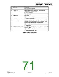
Command
Instruction Code
Description
CHIP_ERASE
0001 0100
Perform flash chip erase (mass erase). The debug interface will be enabled
and no parts of flash will be write-protected after issuing this command. Do not
use any other commands than READ_STATUS until mass erase has
completed. Return 1 status byte to host
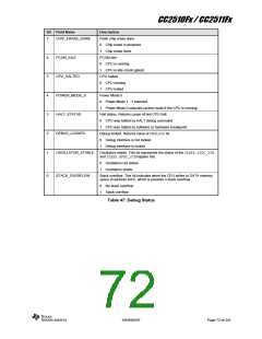
WR_CONFIG
0001 1101
Write configuration data. Return 1 status byte to host. Refer to Table 46 for
details.
RD_CONFIG
GET_PC
0010 0100
0010 1000
0011 0100
0011 1011
0100 0100
0100 1100
Read configuration data. Return value set by WR_CONFIG command
Return value of 16-bit program counter
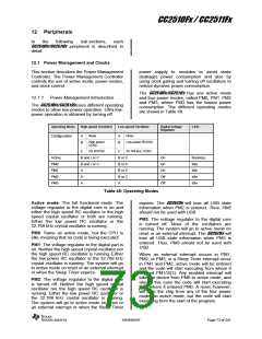
READ_STATUS
SET_HW_BRKPNT
HALT
Read status byte. Refer to Table 47
Set hardware breakpoint
Halt CPU operation. Return 1 status byte to host
RESUME
Resume CPU operation. To run this command, the CPU must have been
halted. Return 1 status byte to host
DEBUG_INSTR
0101 01yy
Run debug instruction. The supplied instruction will be executed by the CPU
without incrementing the program counter. To run this command, the CPU
must have been halted. Return 1 status byte to host.
yy: Number of bytes in the CPU instruction (see Table 37). Valid values are 01,
10, and 11
STEP_INSTR
0101 1100
0110 01 yy
Step CPU instruction. The CPU will execute the next instruction from program
memory and increment the program counter after execution. To run this
command, the CPU must have been halted. Return 1 status byte to host
STEP_REPLACE
Step and replace CPU instruction. The supplied instruction will be executed by
the CPU instead of the next instruction in program memory. The program
counter will be incremented after execution. To run this command, the CPU
must have been halted. Return 1 status byte to host.
yy: Number of bytes in the CPU instruction (see Table 37). Valid values are 01,
10, and 11
GET_CHIP_ID
0110 1000
Return value of 16-bit chip ID (PARTNUM:VERSION).
Table 45: Debug Commands
SWRS055F
Page 70 of 241

 TI [ TEXAS INSTRUMENTS ]