CC2510Fx / CC2511Fx
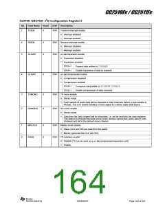
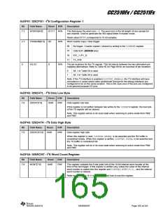
0xDF41: I2SCFG1 - I2S Configuration Register 1
Bit
Field Name
Reset
R/W
Description
7:3
WORDS[4:0]
01111 R/W
This field gives the word size – 1. The word size is the bit-length of one sample for
one channel. Used to generate the WS signal when in master mode.
Reset value 01111 corresponds to 16 bit samples.
Word counter copy / clear trigger
2:1
TRIGNUM[1:0]
00
R/W
00
01
10
11
No trigger. Counter copied / cleared by writing to the I2SWCNTregister
USB SOF (CC2511Fx only)
IOC_1 (P1_3)
T1_CH0
0
IOLOC
0
R/W
The pin locations for the I2S signals. This bit selects between the two alternative pin
mapping alternatives. Refer to Table 50 on Page 89 for an overview of pin locations.
0
Alt. 1 in Table 50 is used
1
Alt. 2 in Table 50 is used
Note: If the I2S interface is enabled (I2SCFG0_ENAB=1), the I2S interface will have
precedence in cases where other peripherals (except for the debug interface) are
configured to be on the same location. This is the case even if the pins are configured
to be general purpose I/O pins.
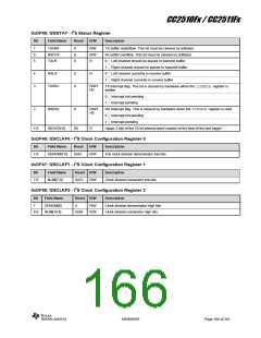
0xDF42: I2SDATL - I2S Data Low Byte
Bit
Field Name
Reset R/W
0x00 R/W
Description
7:0
I2SDAT[7:0]
Data register low byte.
If this register is not written between two writes to the I2SDATHregister, the low byte
of the TX register will be cleared.
Note: This register will be in its reset state when returning to active mode from PM2
and PM3.
0xDF43: I2SDATH - I2S Data High Byte
Bit
Field Name
Reset
R/W
Description
7:0
I2SDAT[15:8]
0x00
R/W
Data register high byte.
When this register is read, I2SSTAT.RXIRQ is de-asserted and the RX buffer is
considered empty. When this register is written, I2SSTAT.TXIRQ is de-asserted and
the TX buffer is considered full.
Note: This register will be in its reset state when returning to active mode from PM2
and PM3.
0xDF44: I2SWCNT - I2S Word Count Register
Bit
Field Name
Reset
R/W
Description
7:0
WCNT[7:0]
0x00
R/W
This register contains the 8 low order bits of the 10-bit internal word counter at the
time of the last trigger. If this register is written (any value),the value of the internal
word counter is copied into this register and I2SSTAT.WCNT[9:8],and the internal
word counter is cleared.
Refer to Section 12.15.11 for details about how to use this register.
SWRS055F
Page 165 of 241

 TI [ TEXAS INSTRUMENTS ]