CC2510Fx / CC2511Fx
12.8 Sleep Timer
The Sleep Timer is used to control when the
CC2510Fx/CC2511Fx exits from PM{0 - 2} and
hence the Sleep Timer can be used to
implement a wake up functionality which
enables CC2510Fx/CC2511Fx to periodically wake
up to active mode and listen for incoming RF
packets.
given
by
WOREVT1.EVENT0
and
WOREVT0.EVENT0, and an exponent value set
by WORCTRL.WOR_RES. When using the low
power RC oscillator to clock the Sleep Timer,
tEvent0 is given by:
750
tEvent0
=
⋅ EVENT0⋅ 25⋅WOR_ RES
fref
Note: The Sleep timer should not be used
in active mode
If the 32.768 kHz crystal oscillator is used to
clock the Sleep Timer, tEvent0 is calculated as
follows:
12.8.1 Sleep Timer Operation
1
tEvent0
=
⋅ EVENT0⋅25⋅WOR _ RES
This section describes the operation of the
timer.
32768
The time from the CC2510Fx/CC2511Fx enters
PM2 until the next Event 0 is programmed to
appear (tSLEEPmin) should be larger than 11.08
ms when fref is 26 MHz and 12 ms when fref is
24 MHz (Sleep Timer clocked by the low
power RC oscillator).
Note: In this section of the document, fRef is
used to denote the reference frequency for
the synthesizer.
For CC2510Fx
and for
fref = fXOSC
fXOSC
CC2511Fx,
fref
=
2
750
t
=
⋅384
When referring to the low power RCOSC,
calibrated values are assumed
SLEEPmin
fref
When the Sleep Timer is clocked by the
The Sleep Timer consists of a 31-bit counter.
The appropriate bits of this counter are
selected according to a resolution setting
determined by the WORCTRL.WOR_RES
register bits. The Sleep Timer is either clocked
by the 32.768 kHz crystal oscillator or by the
low power RC oscillator (fref / 750). The timer
can only be used in PM0, PM1, and PM2.
32.768 kHz crystal oscillator, tSLEEP = 11.72
min
ms (384/32768).
12.8.2 Sleep Timer and Power Modes
Entering PM{0 - 2} and/or updating EVENT0
and has to be aligned to a positive edge on the
32 kHz clock source. The following code
examples should be used in order to update
EVENT0and/or entering PM{0 - 2} correctly:
The Sleep Timer has a programmable timing
event called Event 0. While in PM0, PM1, or
PM2, reaching Event
CC2510Fx/CC2511Fx enter active mode.
0
will make the
Please note that the update rate of the
WORTIME0 register will depend on the Sleep
The time between two consecutive Event 0’s
(tEvent0) is programmed with a mantissa value
Timer
WORCTRL.WOR_RES.
resolution,
configured
through
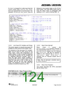
// Alignment of entering PM{0 – 2} to a positive edge on the 32 kHz clock source
char temp = WORTIME0;
while(temp == WORTIME0);
PCON |= 0x01;
// Wait until a positive 32 kHz edge
// Enter PM{0 – 2}
// Alignment of updating EVENT0 to a positive edge on the 32 kHz clock source
char temp = WORTIME0;
while(temp == WORTIME0);
WOREVT1 = desired event0 >> 8;
WOREVT0 = desired event0;
// Wait until a positive 32 kHz edge
// Set EVENT0, high byte
// Set EVENT0, low byte
// Alignment of both updating EVENT0 and entering PM{0 - 2}to a positive edge
// on the 32 kHz clock source
char temp = WORTIME0;
while(temp == WORTIME0);
WOREVT1 = desired event0 >> 8;
WOREVT0 = desired event0;
PCON |= 0x01;
// Wait until a positive 32 kHz edge
// Set EVENT0, high byte
// Set EVENT0, low byte
// Enter PM{0 – 2}
SWRS055F
Page 123 of 241

 TI [ TEXAS INSTRUMENTS ]