CC1110Fx / CC1111Fx
1
Register Conventions
Each SFR is described in a separate table. The table heading is given in the following format:
REGISTER NAME (SFR Address) - Register Description.
Each RF register is described in a separate table. The table heading is given in the following format:
XDATA Address: REGISTER NAME - Register Description
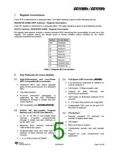
All register descriptions include a symbol denoted R/W describing the accessibility of each bit in the
register. The register values are always given in binary notation unless prefixed by ‘0x’, which
indicates hexadecimal notation.
Symbol
R/W
R
Access Mode
Read/write
Read only
R0
Read as 0
R1
Read as 1
W
Write only
W0
W1
H0
Write as 0
Write as 1
Hardware clear
Hardware set
H1
Table 1: Register Bit Conventions
2
Key Features (in more details)
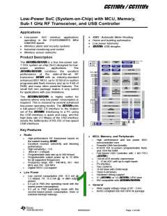
2.1 High-Performance and Low-Power
8051-Compatible Microcontroller
2.3 Full-Speed USB Controller (CC1111Fx )
5 bi-directional endpoints in addition to
control endpoint 0
Optimized 8051 core which typically
gives 8x the performance of a standard
8051
Full-Speed, 12 Mbps transfer rate
Support for Bulk, Interrupt, and
Isochronous endpoints
Two data pointers
In-circuit interactive debugging is
supported by the IAR Embedded
Workbench through a simple two-wire
serial interface
1024 bytes of dedicated endpoint FIFO
memory
8 - 512 byte data packet size supported
SW compatible with CC2510Fx/CC2511Fx
Configurable FIFO size for IN and OUT
direction of endpoint
2.2 8/16/32 KB Non-volatile Program
Memory and 1/2/4 kB Data Memory
2.4 I2S Interface
Industry standard I2S interface for
transfer of digital audio data
8, 16, or 32 KB of non-volatile flash
memory,
in-system
programmable
through a simple two-wire interface or
by the 8051 core
Full duplex
Mono and stereo support
Minimum flash memory endurance:
1000 write/erase cycles
Configurable sample rate and sample
size
Programmable read and write lock of
portions of flash memory for software
security
Support for -law compression and
expansion
1, 2, or 4 kB of internal SRAM
SWRS033H
Page 5 of 246

 TI [ TEXAS INSTRUMENTS ]