bq4285E/L
INTF - Interrupt Request Flag
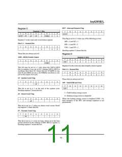
Register C
Register C Bits
7
6
-
5
-
4
-
3
-
2
-
1
-
0
-
7
6
5
4
3
0
2
1
0
0
0
INTF
INTF PF
AF
UF
32KE
This flag is set to a 1 when any of the following is true:
AIE = 1 and AF = 1
Register C is the read-only event status register.
Bits 0–3 - Unused Bits
PIE = 1 and PF = 1
7
-
6
-
5
-
4
-
3
0
2
-
1
0
0
0
UIE = 1 and UF = 1
Reading register C clears this bit.
These bits are always set to 0.
Register D
32KE–32KHz Enable Output
Register D Bits
7
6
0
5
0
4
0
3
0
2
0
1
0
0
0
7
-
6
-
5
-
4
-
3
-
2
1
-
0
-
VRT
32KE
Register D is the read-only data integrity status register.
This bit may be set to a 1 only when the OSC2–OSC0
bits in register A are set to 011. Setting OSC2–OSC0 to
anything other than 011 clears this bit. If SQWE in reg-
ister B and 32KE are set, a 32.768KHz waveform is out-
put on the square wave pin.
Bits 0–6 - Unused Bits
7
-
6
0
5
0
4
0
3
0
2
0
1
0
0
0
UF - Update-Event Flag
These bits are always set to 0.
7
-
6
-
5
-
4
3
-
2
-
1
-
0
-
VRT - Valid RAM and Time
UF
7
6
-
5
-
4
-
3
-
2
-
1
-
0
-
VRT
This bit is set to a 1 at the end of the update cycle.
Reading register C clears this bit.
1 = Valid backup energy source
0 = Backup energy source is depleted
AF - Alarm Event Flag
When the backup energy source is depleted (VRT = 0),
data integrity of the RTC and storage registers is not
guaranteed.
7
-
6
-
5
4
-
3
-
2
-
1
-
0
-
AF
This bit is set to a 1 when an alarm event occurs. Read-
ing register C clears this bit.
PF - Periodic Event Flag
7
-
6
5
-
4
-
3
-
2
-
1
-
0
-
PF
This bit is set to a 1 every tPI time, where tPI is the time
period selected by the settings of RS0–RS3 in register A.
Reading register C clears this bit.
11

 TI [ TEXAS INSTRUMENTS ]