bq24735
www.ti.com
SLUSAK9 –SEPTEMBER 2011
Converter Operation
The synchronous buck PWM converter uses a fixed frequency voltage mode control scheme and internal type III
compensation network. The LC output filter gives a characteristic resonant frequency
1
¦
=
o
2p LoCo
(3)
The resonant frequency fo is used to determine the compensation to ensure there is sufficient phase margin and
gain margin for the target bandwidth. The LC output filter should be selected to give a resonant frequency of
10–20 kHz nominal for the best performance. Suggest component value as charge current of 750kHz default
switching frequency is shown in Table 7.
Ceramic capacitors show a dc-bias effect. This effect reduces the effective capacitance when a dc-bias voltage is
applied across a ceramic capacitor, as on the output capacitor of a charger. The effect may lead to a significant
capacitance drop, especially for high output voltages and small capacitor packages. See the manufacturer's data
sheet about the performance with a dc bias voltage applied. It may be necessary to choose a higher voltage
rating or nominal capacitance value in order to get the required value at the operating point.
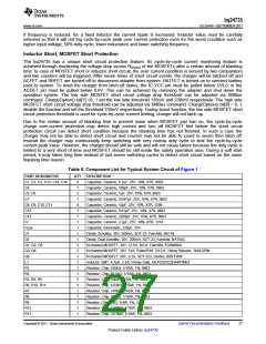
Table 7. Suggest Component Value as Charge Current of Default 750kHz
Switching Frequency
Charge Current
Output Inductor Lo (µH)
Output Capacitor Co (µF)
Sense Resistor (mΩ)
2A
6.8 or 8.2
20
3A
5.6 or 6.8
20
4A
3.3 or 4.7
20
6A
3.3
30
8A
2.2
40
10
10
10
10
10
The bq24735 has three loops of regulation: input current, charge current and charge voltage. The three loops are
brought together internally at the error amplifier. The maximum voltage of the three loops appears at the output
of the error amplifier EAO. An internal saw-tooth ramp is compared to the internal error control signal EAO (see
Figure 17) to vary the duty-cycle of the converter. The ramp has offset of 200mV in order to allow 0% duty-cycle.
When the battery charge voltage approaches the input voltage, EAO signal is allowed to exceed the saw-tooth
ramp peak in order to get a 100% duty-cycle. If voltage across BTST and PHASE pins falls below 4.3V, a refresh
cycle starts and low-side n-channel power MOSFET is turned on to recharge the BTST capacitor. It can achieve
duty cycle of up to 99.5%.
Continuous Conduction Mode (CCM)
With sufficient charge current the bq24735’s inductor current never crosses zero, which is defined as continuous
conduction mode. The controller starts a new cycle with ramp coming up from 200mV. As long as EAO voltage is
above the ramp voltage, the high-side MOSFET (HSFET) stays on. When the ramp voltage exceeds EAO
voltage, HSFET turns off and low-side MOSFET (LSFET) turns on. At the end of the cycle, ramp gets reset and
LSFET turns off, ready for the next cycle. There is always break-before-make logic during transition to prevent
cross-conduction and shoot-through. During the dead time when both MOSFETs are off, the body-diode of the
low-side power MOSFET conducts the inductor current.
During CCM mode, the inductor current is always flowing and creates a fixed two-pole system. Having the
LSFET turn-on keeps the power dissipation low, and allows safely charging at high currents.
Discontinuous Conduction Mode (DCM)
During the HSFET off time when LSFET is on, the inductor current decreases. If the current goes to zero, the
converter enters Discontinuous Conduction Mode. Every cycle, when the voltage across SRP and SRN falls
below 5mV (0.5A on 10mΩ), the under current-protection comparator (UCP) turns off LSFET to avoid negative
inductor current, which may boost the system via the body diode of HSFET.
During the DCM mode the loop response automatically changes. It changes to a single pole system and the pole
is proportional to the load current.
Copyright © 2011, Texas Instruments Incorporated
Submit Documentation Feedback
25
Product Folder Link(s) :bq24735

 TI [ TEXAS INSTRUMENTS ]