ꢀ ꢁꢂ ꢃ ꢄ ꢅ ꢂ ꢆ ꢀꢁ ꢂꢃ ꢄꢅ ꢇ
SLUS553D − MAY 2003 − REVISED JULY 2005
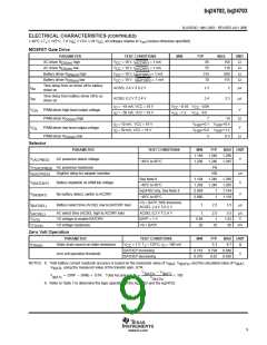
ELECTRICAL CHARACTERISTICS (CONTINUED)
(−40°C ≤ T ≤ 125°C, 7.0 V
≤ VCC ≤ 28 V , all voltages relative to V ) (unless otherwise specified)
J
DC
DC
ss
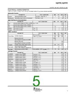
MOSFET Gate Drive
PARAMETER
TEST CONDITIONS
MIN
TYP
MAX
150
UNIT
Ω
AC driver R
AC driver R
high
low
V
CC
V
CC
V
CC
V
CC
= 18 V, I
= 18 V, I
= 18 V, I
= 1 mA
= 1 mA
85
55
DS(on)
(ACDRV)
(ACDRV)
(BATDRV)
110
600
115
Ω
DS(on)
Battery driver R
high
= 1 mA
= 1 mA
315
70
Ω
DS(on)
DS(on)
Battery driver R
low
= 18 V, I
(BATDRV)
Ω
Time delay from ac driver off to battery
driver on
t
t
ACSEL 2.4 V ⇓ 0.2 V
ACSEL 0.2 V ⇑ 2.4 V
1.2
2.4
2
µs
µs
da
Time delay from battery driver off to ac
driver on
3.3
db
I
I
= −10 mA, VCC = 18 V
V
−0.18
V
−0.09
−0.8
7
O
CC
CC
V
PWM driver high-level output voltage
V
OH
OL
= −50 mA, VCC = 18 V
V
CC
−1.2
V
CC
O
PWM driver R
DS(on)
high
14
+0.4
+1.2
8.5
Ω
I
I
= 10 mA, VCC = 18 V
= 50 mA, VCC = 18 V
V
+0.1
+0.6
5
V
V
O
HSP
HSP
V
PWM driver low-level output voltage
V
V
O
HSP
HSP
PWM driver R
DS(on)
low
Ω
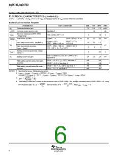
Selector
PARAMETER
TEST CONDITIONS
MIN
TYP
1.246
1.246
1%
MAX UNIT
1.194
1.208
1.286
V
V
AC presence detect voltage
V
(ACPRES)
−40°C to 85°C
1.285
AC presence hysteresis
IT(ACPRES)
d(ACPRES)
t
Deglitch delay for adapter insertion
100
µs
See Note 8
1.194
1.208
0.869
0.880
1.246
1.246
1
1.286
V
V
Battery depletion ALARM trip voltage
No battery detect, switch to ACDRV
V
(BATDEP)
−40°C to 85°C
1.285
bq24702 only, See Note 8
−40°C to 85°C
1.144
V
(NOBAT)
1
1.118
VS < BATP, 50% threshold,
ACSEL 2.4 V ⇓ 0.2 V
t
t
Battery select time (ACSEL low to BATDRV low)
1
2.5
3.5
µs
(BATSEL)
AC select time (ACSEL high to ACDRV low)
VS voltage to enable BATDRV
VS voltage hysteresis
ACSEL 0.2 V ⇑ 2.4 V
BATP = 1 V
1
0.98
20
2.5
1
3.5
1.02
85
µs
V
(ACSEL)
V
(VS)
V
VS > BATP
35
mV
IT(VS)
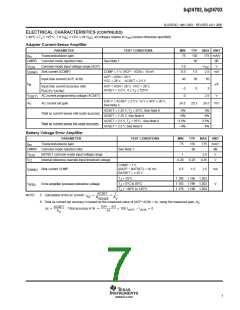
Zero Volt Operation
PARAMETER
TEST CONDITIONS
MIN
TYP
5.3
MAX UNIT
r
Static drain source on-state resistance
V
CC
= 7 V, T = 125°C, I = 100 mA
8.7
0.840
0.656
Ω
DS(on)
J
O
BATDEP increasing
BATDEP decreasing
0.743
0.570
0.794
0.62
zero volt operation threshold
V
NOTES: 8. Total battery current readback accuracy is based on the measured value of V
, V
, and the calculated value of V ,
IBAT
IBAT IBATm
V
, using the measured value of the transfer gain, GTR.
V
IBATc
* V
IBATm
IBATm
V
IBATc
(
)
V
+ SRP * SRN GTR Total Accuracy in % +
100
IBATc
9. Refer to Table 1 to determine the logic operation of the bq24702 and the bq24703.
9
www.ti.com

 TI [ TEXAS INSTRUMENTS ]