bq24160, bq24161
bq24163, bq24168
SLUSAO0A –NOVEMBER 2011–REVISED MARCH 2012
www.ti.com
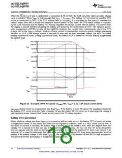
When the CE bit is a 0 and a valid source is connected to IN or USB, the buck converter starts up and a charge
cycle is initiated. When VBAT is high enough that VSYS > VSYS(REG), the battery FET is turned on and the SYS
output is connected to BAT. If the SYS voltage falls to VSYS(REG), it is regulated to that point to maintain the
system output even with a deeply discharged or absent battery. In this mode, the SYS output voltage is regulated
by the buck converter and the battery FET linearly regulates the charge current into the battery. The current from
the supply is shared between charging the battery and powering the system load at SYS. The dynamic power-
path management (DPPM) circuitry of the bq2416x monitors the current limits continuously, and if the SYS
voltage falls to the VMINSYS voltage, it adjusts charge current to maintain the minimum system voltage and supply
the load on SYS. If the charge current is reduced to zero and the load increases further, the bq2416x enters
battery-supplement mode. During supplement mode, the battery FET is turned on and the battery supplements
the system load.
2000 mA
1800 mA
ISYS
800 mA
mA
0
1500 mA
~850 mA
IIN
0mA
1A
IBAT
0mA
-200 mA
VSYS(REG)
VMINSYS
DPPM loop active
VOUT
~3.1V
Supplement
Mode
Figure 23. Example DPPM Response (VSupply=5V, VBAT = 3.1V, 1.5A Input current limit)
VBAT(REG) should never be programmed less than VBAT. If the battery is ever 5% above the regulation threshold,
the battery OVP circuit shuts the PWM converter off and the battery FET is turned on to discharge the battery to
safe operating levels. Battery OVP errors are reported in the I2C status registers.
Battery Only Connected
When a battery voltage less than VBATUVLO is connected with no input source, the battery FET is turned on similar
to supplement mode. In this mode, the current is not regulated; however, there is a short circuit current limit. If
the short circuit limit is reached, the battery FET is turned off for the deglitch time. After the deglitch time, the
battery FET is turned on to test and see if the short has been removed. If it has not, the FET turns off and the
process repeats until the short is removed. This process is to protect the internal FET from over current. If an
external FET is used for discharge, the body diode prevents the load on SYS from being disconnected from the
battery. If the battery voltage is less than VBATUVLO, the battery FET (Q6) remains off and BAT is high-impedance.
This prevents further discharging of deeply-discharged batteries.
18
Submit Documentation Feedback
Copyright © 2011–2012, Texas Instruments Incorporated
Product Folder Link(s): bq24160 bq24161 bq24163 bq24168

 TI [ TEXAS INSTRUMENTS ]