bq24160, bq24161
bq24163, bq24168
www.ti.com
SLUSAO0A –NOVEMBER 2011–REVISED MARCH 2012
Both inputs are protected by a cycle-by-cycle current limit that is sensed through the high-side MOSFETs for Q1
and Q2. The threshold for the current limit is set to a nominal 5A peak current. The inputs also utilize an input
current limit that limits the current from the power source.
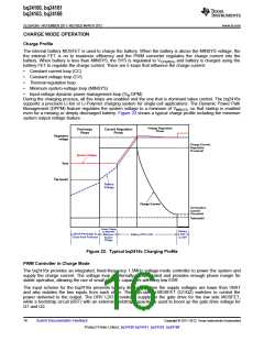
Battery Charging Process
When the battery is deeply discharged or shorted (VBAT < VBATSHRT), the bq2416x applies IBATSHRT to close the
pack protector switch and bring the battery voltage up to acceptable charging levels. During this time, the battery
FET is linearly regulated and the system output is regulated to VSYS(REG). Once the battery rises above VBATSHRT
,
the charge current is regulated to the value set in the I2C register. The battery FET is linearly regulated to
maintain the system voltage at VSYS(REG). Under normal conditions, the time spent in this region is a very short
percentage of the total charging time, so the linear regulation of the charge current does not affect the overall
charging efficiency for very long. If the die temperature does rise, the thermal regulation circuit reduces the
charge current to maintain a die temperature less than 120°C. If the current limit for the SYS output is reached
(limited by the input current limit, or VIN_DPM), the SYS output drops to the VMINSYS output voltage. When this
happens, the charge current is reduced to provide the system with all the current that is needed while
maintaining the minimum system voltage. If the charge current is reduced to 0mA, pulling further current from
SYS causes the output to fall to the battery voltage and enter supplement mode. (See the Dynamic Power Path
Management section for more details.)
Once the battery is charged enough so that the system voltage begins to rise above VSYS(REG), the battery FET is
turned on fully and the battery is charged with the full programmed charge current set by the I2C interface,
ICHARGE. The slew rate for the fast-charge current is controlled to minimize current and voltage overshoot during
transients. The charge current is regulated to ICHARGE until the battery is charged to the regulation voltage. Once
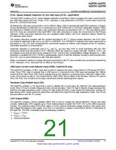
the battery voltage is close to the regulation voltage, VBATREG, the charge current is tapered down as shown in
Figure 22 while the SYS output remains connected to the battery. The voltage-regulation feedback occurs by
monitoring the battery-pack voltage between the BAT and PGND pins. The bq2416x is a fixed single-cell voltage
version, with adjustable regulation voltage (3.5V to 4.44V), programmed using the I2C interface.
The bq2416x monitors the charging current during the voltage-regulation phase. Once the termination threshold,
ITERM, is detected and the battery voltage is above the recharge threshold, the bq2416x terminates charge and
turns off the battery charging FET. The system output is regulated to the VSYS(REG) and supports the full current
available from the input and the battery supplement mode is available. (See the Dynamic Power Path
Management section for more details.) The termination current level is programmable. To disable the charge
current termination, the host sets the charge termination bit (TE) of charge control register to 0, refer to I2C
section for details.
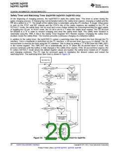
A new charge cycle is initiated when one of the following conditions is detected:
1. The battery voltage falls below the VBATREG-VRCH threshold.
2. VSUPPLY toggle
3. CE bit toggle or RESET bit is set
4. HI-Z bit toggle
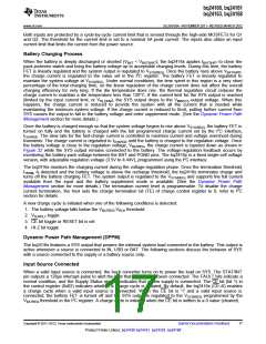
Dynamic Power Path Management (DPPM)
The bq2416x features a SYS output that powers the external system load connected to the battery. This output is
active whenever a source is connected to IN, USB or BAT. The following sections discuss the behavior of SYS
with a source connected to the supply or a battery source only.
Input Source Connected
When a valid input source is connected, the buck converter turns on to power the load on SYS. The STAT/INT
pin outputs a 128µs interrupt pulse to alert the host that an input has been connected. The FAULT bits indicate a
normal condition, and the Supply Status register indicates that a new supply is connected. The CE bit (bit 1) in
the control register (0x02) indicates whether a charge cycle is initiated. By default, the bq2416x (CE=0) enables
a charge cycle when a valid input source is connected. When the CE bit is '1' and a valid input source is
connected, the battery FET is turned off and the SYS output is regulated to the VSYS(REG) programmed by the
VBATREG threshold in the I2C register. A charge cycle is initiated when the CE bit is written to a 0 value (cleared).
Copyright © 2011–2012, Texas Instruments Incorporated
Submit Documentation Feedback
17
Product Folder Link(s): bq24160 bq24161 bq24163 bq24168

 TI [ TEXAS INSTRUMENTS ]