AM3359, AM3358, AM3357
AM3356, AM3354, AM3352
SPRS717F –OCTOBER 2011–REVISED APRIL 2013
www.ti.com
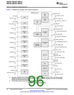
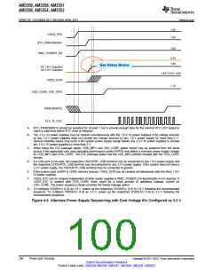
Figure 3-1 illustrates an example of the external capacitors.
AM335x Device
VDDS_PLL_MPU
CVDDS_PLL_MPU
MPU
PLL
VDD_MPU
MPU
CVDD_MPU
VDDS_PLL_CORE_LCD
CVDDS_PLL_CORE_LCD
CORE
PLL
LCD
PLL
VDD_CORE
CVDD_CORE
CORE
CAP_VBB_MPU
CCAP_VBB_MPU
VDDS
IO
CVDDS
VDDS_SRAM_MPU_BB
CVDDS_SRAM_MPU_BB
VDDSHV1
IOs
MPU SRAM
LDO
CVDDSHV1
Back Bias
LDO
CAP_VDD_SRAM_MPU
CCAP_VDD_SRAM_MPU
VDDSHV2
IOs
CVDDSHV2
CVDDSHV3
CVDDSHV4
CVDDSHV5
CVDDSHV6
CVDDS_DDR
CVDDS_RTC
VDDS_SRAM_CORE_BG
CVDDS_SRAM_CORE_BG
VDDSHV3
IOs
CORE SRAM
LDO
Band Gap
Reference
CAP_VDD_SRAM_CORE
CCAP_VDD_SRAM_CORE
VDDSHV4
IOs
VDDA_3P3V_USBx
CVDDA_3P3V_USBx
VDDSHV5
IOs
VSSA_USB
USB PHYx
VDDA_1P8V_USBx
VDDSHV6
IOs
CVDDA_1P8V_USBx
VSSA_USB
VDDA_ADC
VDDS_DDR
IOs
CVDDA_ADC
ADC
VDDS_RTC
IOs
VSSA_ADC
VDDS_OSC
CVDDS_OSC
VDDS_PLL_DDR
CVDDS_PLL_DDR
DDR
PLL
CAP_VDD_RTC
CCAP_VDD_RTC
RTC
A. Decoupling capacitors must be placed as closed as possible to the power terminal. Choose the ground located
closest to the power pin for each decoupling capacitor. In case of interconnecting powers, first insert the decoupling
capacitor and then interconnect the powers.
B. The decoupling capacitor value depends on the board characteristics.
Figure 3-1. External Capacitors
96
Device Operating Conditions
Copyright © 2011–2013, Texas Instruments Incorporated
Submit Documentation Feedback
Product Folder Links: AM3359 AM3358 AM3357 AM3356 AM3354 AM3352

 TI [ TEXAS INSTRUMENTS ]