AM3359, AM3358, AM3357
AM3356, AM3354, AM3352
SPRS717F –OCTOBER 2011–REVISED APRIL 2013
www.ti.com
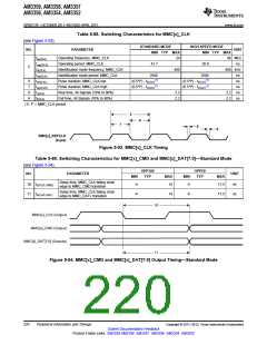
Table 5-88. Switching Characteristics for MMC[x]_CLK
(see Figure 5-93)
STANDARD MODE
MIN TYP MAX
HIGH-SPEED MODE
NO.
PARAMETER
UNIT
MIN TYP MAX
fop(CLK)
Operating frequency, MMC_CLK
Operating period: MMC_CLK
24
48 MHz
ns
tcop(CLK)
41.7
20.8
5
fid(CLK)
Identification mode frequency, MMC_CLK
Identification mode period: MMC_CLK
Pulse duration, MMC_CLK low
400
400 kHz
ns
tcid(CLK)
2500
2500
(1)
(1)
6
7
8
9
tw(CLKL)
tw(CLKH)
tr(CLK)
(0.5*P) - tf(CLK)
(0.5*P) - tf(CLK)
ns
(1)
(1)
Pulse duration, MMC_CLK high
Rise time, All Signals (10% to 90%)
Fall time, All Signals (10% to 90%)
(0.5*P) - tr(CLK)
(0.5*P) - tr(CLK)
ns
2.2
2.2
2.2 ns
2.2 ns
tf(CLK)
(1) P = MMC_CLK period.
5
6
7
8
9
RMII[x]_REFCLK
(Input)
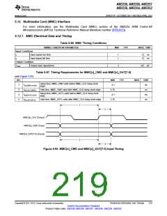
Figure 5-93. MMC[x]_CLK Timing
Table 5-89. Switching Characteristics for MMC[x]_CMD and MMC[x]_DAT[7:0]—Standard Mode
(see Figure 5-94)
OPP100
TYP
OPP50
TYP
NO.
PARAMETER
UNIT
MIN
MAX
MIN
MAX
Delay time, MMC_CLK falling clock
edge to MMC_CMD transition
10 td(CLKL-CMD)
11 td(CLKL-DAT)
-4
14
-4
17.5
ns
ns
Delay time, MMC_CLK falling clock
edge to MMC_DATx transition
-4
14
-4
17.5
10
MMC[x]_CLK (Output)
MMC[x]_CMD (Output)
MMC[x]_DAT[7:0] (Outputs)
11
Figure 5-94. MMC[x]_CMD and MMC[x]_DAT[7:0] Output Timing—Standard Mode
220
Peripheral Information and Timings
Copyright © 2011–2013, Texas Instruments Incorporated
Submit Documentation Feedback
Product Folder Links: AM3359 AM3358 AM3357 AM3356 AM3354 AM3352

 TI [ TEXAS INSTRUMENTS ]