ADS1299
www.ti.com
SBAS499A –JULY 2012–REVISED AUGUST 2012
POWER-UP SEQUENCING
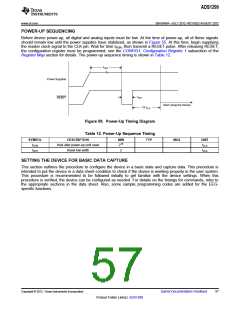
Before device power-up, all digital and analog inputs must be low. At the time of power-up, all of these signals
should remain low until the power supplies have stabilized, as shown in Figure 55. At this time, begin supplying
the master clock signal to the CLK pin. Wait for time tPOR, then transmit a RESET pulse. After releasing RESET,
the configuration register must be programmed; see the CONFIG1: Configuration Register 1 subsection of the
Register Map section for details. The power-up sequence timing is shown in Table 12.
tPOR
Power Supplies
tRST
RESET
Start Using the Device
18 tCLK
Figure 55. Power-Up Timing Diagram
Table 12. Power-Up Sequence Timing
SYMBOL
tPOR
DESCRIPTION
Wait after power-up until reset
Reset low width
MIN
216
2
TYP
MAX
UNIT
tCLK
tRST
tCLK
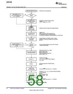
SETTING THE DEVICE FOR BASIC DATA CAPTURE
This section outlines the procedure to configure the device in a basic state and capture data. This procedure is
intended to put the device in a data sheet condition to check if the device is working properly in the user system.
This procedure is recommended to be followed initially to get familiar with the device settings. When this
procedure is verified, the device can be configured as needed. For details on the timings for commands, refer to
the appropriate sections in the data sheet. Also, some sample programming codes are added for the EEG-
specific functions.
Copyright © 2012, Texas Instruments Incorporated
Submit Documentation Feedback
57
Product Folder Link(s): ADS1299

 TI [ TEXAS INSTRUMENTS ]