ADS1274
ADS1278
www.ti.com
SBAS367F –JUNE 2007–REVISED FEBRUARY 2011
POWER-DOWN (PWDN)
3. Detect for non-zero data in the powered-up
channel.
The channels of the ADS1274/78 can be
independently powered down by use of the PWDN
inputs. To enter the power-down mode, hold the
respective PWDN pin low for at least two CLK cycles.
To exit power-down, return the corresponding PWDN
pin high. Note that when all channels are powered
down, the ADS1274/78 enters a microwatt (μW)
power state where all internal biasing is disabled. In
this state, the TEST[1:0] input pins must be driven; all
other input pins can float. The ADS1274/78 outputs
remain driven.
After powering up one or more channels, the
channels are synchronized to each other. It is not
necessary to use the SYNC pin to synchronize them.
When a channel is powered down in TDM data
format, the data for that channel are either forced to
zero (fixed-position TDM data mode) or replaced by
shifting the data from the next channel into the
vacated data position (dynamic-position TDM data
mode).
In Discrete data format, the data are always forced to
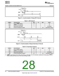
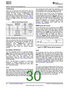
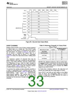
As shown in Figure 75 and Table 13, a maximum of
130 conversion cycles must elapse for SPI interface,
and 129 conversion cycles must elapse for
Frame-Sync, before reading data after exiting
power-down. Data from channels already running are
not affected. The user software can perform the
required delay time in any of the following ways:
zero.
When
powering-up
a
channel
in
dynamic-position TDM data format mode, the channel
data remain packed until the data are ready, at which
time the data frame is expanded to include the
just-powered channel data. See the Data Format
section for details.
1. Count the number of data conversions after
taking the PWDN pin high.
2. Delay 129/fDATA or 130/fDATA after taking the
PWDN pins high, then read data.
· · ·
· · ·
CLK
tPWDN
tNDR
PWDN
DRDY/FSYNC(1)
DOUT
(Discrete Data Output Mode)
Post Power-Up Data
Normal Position
DOUT1
(TDM Mode, Dynamic Position)
Normal Position
Data Shifts Position
DOUT1
(TDM Mode, Fixed Position)
Normal Position
Data Remains in Position
Normal Position
(1) In SPI protocol, the timing occurs on the falling edge of DRDY/FSYNC. Powering down all channels forces DRDY/FSYNC high.
Figure 75. Power-Down Timing
Table 13. Power-Down Timing
SYMBOL
tPWDN
tNDR
DESCRIPTION
MIN
2
TYP
MAX
UNITS
PWDN pulse width to enter Power-Down mode
Time for new data ready (SPI)
Time for new data ready (Frame-Sync)(1)
CLK periods
129
128
130
129
Conversions (1/fDATA
)
)
tNDR
Conversions (1/fDATA
(1) FSYNC clock running prior to the rising edge of PWDN. If PWDN is asynchronous to the FSYNC clock, tNDR-FS varies from 127 to 128
conversions. If PWDN is made synchronous to FSYNC, then tNDR-FS is stable.
© 2007–2011, Texas Instruments Incorporated
Submit Documentation Feedback
29
Product Folder Link(s): ADS1274 ADS1278

 TI [ TEXAS INSTRUMENTS ]