ADC0801, ADC0802
ADC0803, ADC0804, ADC0805
SNOSBI1B –NOVEMBER 2009–REVISED FEBRUARY 2013
www.ti.com
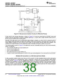
Figure 63. Microprocessor Interface Circuitry for Differential Preamp
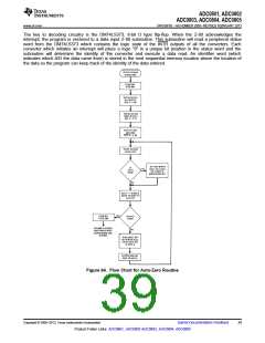
A flow chart for the zeroing subroutine is shown in Figure 64. It must be noted that the ADC0801 series will
output an all zero code when it converts a negative input [VIN(−) ≥ VIN(+)]. Also, a logic inversion exists as all of
the I/O ports are buffered with inverting gates.
Basically, if the data read is zero, the differential output voltage is negative, so a bit in Port B is cleared to pull VX
more negative which will make the output more positive for the next conversion. If the data read is not zero, the
output voltage is positive so a bit in Port B is set to make VX more positive and the output more negative. This
continues for 8 approximations and the differential output eventually converges to within 5 mV of zero.
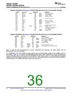
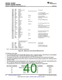
The actual program is given in Figure 65. All addresses used are compatible with the BLC 80/10 microcomputer
system. In particular:
•
•
•
•
•
Port A and the ADC0801 are at port address E4
Port B is at port address E5
Port C is at port address E6
PPI control word port is at port address E7
Program Counter automatically goes to ADDR:3C3D upon acknowledgment of an interrupt from the ADC0801
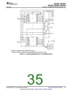
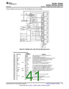
Multiple A/D Converters in a Z-80 Interrupt Driven Mode
In data acquisition systems where more than one A/D converter (or other peripheral device) will be interrupting
pro- gram execution of a microprocessor, there is obviously a need for the CPU to determine which device
requires servicing. Figure 66 and the accompanying software is a method of determining which of 7 ADC0801
converters has completed a conversion (INTR asserted) and is requesting an interrupt. This circuit allows starting
the A/D converters in any sequence, but will input and store valid data from the converters with a priority
sequence of A/D 1 being read first, A/D 2 second, etc., through A/D 7 which would have the lowest priority for
data being read. Only the converters whose INT is asserted will be read.
38
Submit Documentation Feedback
Copyright © 2009–2013, Texas Instruments Incorporated
Product Folder Links: ADC0801, ADC0802 ADC0803, ADC0804, ADC0805

 TI [ TEXAS INSTRUMENTS ]