ꢀ
ꢁ
ꢅ
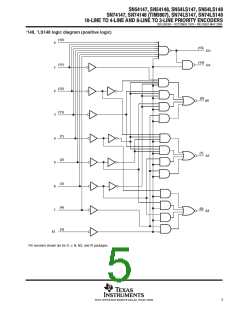
ꢔ
ꢂ
ꢃ
ꢇ
ꢃ
ꢄ
ꢐ
ꢄ
ꢃ
ꢈ
ꢃ
ꢇ
ꢅ
ꢆ
ꢉ
ꢑ
ꢀ
ꢁ
ꢌ
ꢒ
ꢂ
ꢍ
ꢃ
ꢍ
ꢕ
ꢄ
ꢎ
ꢃ
ꢅ
ꢋ
ꢇ
ꢆ
ꢀ
ꢀ
ꢑ
ꢁ
ꢂ
ꢃ
ꢗ
ꢃ
ꢈ
ꢈ
ꢀ
ꢀ
ꢄ
ꢗ
ꢄ
ꢃ
ꢃ
ꢅ
ꢘ
ꢅ
ꢆ
ꢆ
ꢀ
ꢀ
ꢁ
ꢁ
ꢙ
ꢂ
ꢅ
ꢒ
ꢃ
ꢃ
ꢈ
ꢈ
ꢔ
ꢀ
ꢀ
ꢑ
ꢄ
ꢄ
ꢗ
ꢃ
ꢃ
ꢀ
ꢇ
ꢇ
ꢀ
ꢁ
ꢅ
ꢃ
ꢄ
ꢃ
ꢅ
ꢆ
ꢀ
ꢁ
ꢊ
ꢋ
ꢏ
ꢆ
ꢁ
ꢅ
ꢄ
ꢎ
ꢐ
ꢈꢋ
ꢁ
ꢑ
ꢊ ꢒ
ꢃ
ꢐ
ꢈ
ꢋ
ꢁ
ꢑ
ꢓ
ꢁ
ꢋ
ꢁ
ꢊ
ꢐ
ꢈ
ꢁ
ꢖ
ꢋ
ꢒ
ꢋ
ꢊ
ꢑ
ꢁ
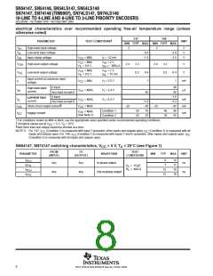
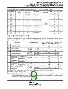
SDLS053B − OCTOBER 1976 − REVISED MAY 2004
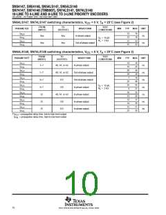
SN54148, SN74148 switching characteristics, V
= 5 V, T = 255C (see Figure 1)
CC
A
FROM
TO
TEST
†
PARAMETER
WAVEFORM
In-phase output
Out-of-phase output
Out-of-phase output
In-phase output
In-phase output
In-phase output
In-phase output
MIN
TYP
MAX
UNIT
ns
(INPUT)
(OUTPUT)
CONDITIONS
t
t
t
t
t
t
t
t
t
t
t
t
t
t
10
9
15
14
19
19
10
25
30
25
15
15
12
15
15
30
PLH
PHL
PLH
PHL
PLH
PHL
PLH
PHL
PLH
PHL
PLH
PHL
PLH
PHL
1–7
1–7
0–7
0–7
EI
A0, A1, or A2
13
12
6
A0, A1, or A2
ns
EO
GS
ns
14
18
14
10
10
8
C
R
= 15 pF,
= 400 Ω
L
L
ns
A0, A1, or A2
GS
ns
EI
ns
10
10
17
EI
EO
ns
†
t
t
= propagation delay time, low-to-high-level output.
= propagation delay time, high-to-low-level output.
PLH
PHL
electrical characteristics over recommended operating free-air temperature range (unless
otherwise noted)
SN54LS’
SN74LS’
†
PARAMETER
TEST CONDITIONS
UNIT
‡
‡
MIN TYP
MAX
MIN TYP
MAX
V
V
V
High-level input voltage
Low-level input voltage
Input clamp voltage
2
2
V
V
V
IH
0.7
0.8
IL
V
= MIN,
= MIN,
I = −18 mA
−1.5
−1.5
IK
CC
I
V
V
V
= 2 V,
= −400 µA
CC
IL
IH
V
High-level output voltage
2.5
3.4
2.7
3.4
V
OH
OL
= 0.8 V,
I
OH
V
V
V
= MIN,
= 2 V,
I
= 4 mA
= 8 mA
0.25
0.4
0.25
0.35
0.4
0.5
0.2
0.1
CC
IH
IL
OL
OL
V
Low-level output voltage
V
I
= V MAX
IL
Input current at
maximum input
voltage
’LS148 inputs 1–7
All other inputs
0.2
0.1
I
I
V
CC
= MAX,
V = 7 V
I
mA
I
’LS148 inputs 1–7
All other inputs
40
20
40
20
High-level input
current
V
V
= MAX,
= MAX,
V = 2.7 V
I
µA
IH
CC
’LS148 inputs 1–7
All other inputs
−0.8
−0.4
−100
20
−0.8
−0.4
−100
20
Low-level input
current
I
I
I
V = 0.4 V
I
mA
mA
mA
IL
CC
§
Short-circuit output current
V
V
= MAX
= MAX
−20
−20
OS
CC
CC
Condition 1
Condition 2
12
10
12
10
CC
Supply current
(See Note 6)
17
17
†
For conditions shown as MIN or MAX, use the appropriate value specified under recommended operating conditions.
‡
§
All typical values are at V
Not more than one output should be shorted at a time.
= 5 V, T = 25°C.
CC
A
NOTE 6: For ’LS147, I
CC
(Condition 1) is measured with input 7 grounded, other inputs and outputs open; I
(Condition 2) is measured with
CC
(Condition 1) is measured with inputs 7 and EI grounded, other inputs and outputs open;
all inputs and outputs open. For ’LS148, I
CC
I
(Condition 2) is measured with all inputs and outputs open.
CC
9
POST OFFICE BOX 655303 • DALLAS, TEXAS 75265

 TI [ TEXAS INSTRUMENTS ]