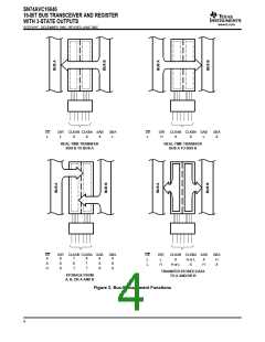
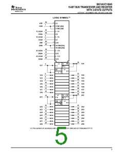
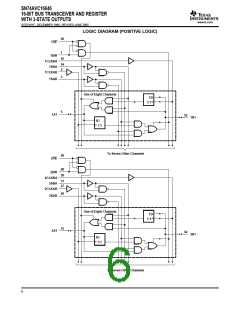
SN74AVC16646
16-BIT BUS TRANSCEIVER AND REGISTER
WITH 3-STATE OUTPUTS
www.ti.com
SCES181F–DECEMBER 1998–REVISED JUNE 2005
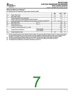
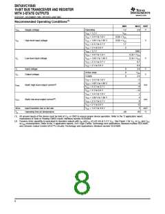
Recommended Operating Conditions(1)
MIN
1.2
MAX UNIT
VCC
Supply voltage
Operating
3.6
V
VCC = 1.2 V
VCC
VCC = 1.4 V to 1.6 V
VCC = 1.65 V to 1.95 V
VCC = 2.3 V to 2.7 V
VCC = 3 V to 3.6 V
VCC = 1.2 V
0.65 × VCC
0.65 × VCC
1.7
VIH
High-level input voltage
V
2
GND
VCC = 1.4 V to 1.6 V
VCC = 1.65 V to 1.95 V
VCC = 2.3 V to 2.7 V
VCC = 3 V to 3.6 V
0.35 × VCC
VIL
Low-level input voltage
0.35 × VCC
V
0.7
0.8
3.6
VCC
3.6
–2
–4
–8
–12
2
VI
Input voltage
0
0
0
V
V
Active state
VO
Output voltage
3-state
VCC = 1.4 V to 1.6 V
VCC = 1.65 V to 1.95 V
VCC = 2.3 V to 2.7 V
VCC = 3 V to 3.6 V
VCC = 1.4 V to 1.6 V
VCC = 1.65 V to 1.95 V
VCC = 2.3 V to 2.7 V
VCC = 3 V to 3.6 V
VCC = 1.4 V to 3.6 V
IOHS
Static high-level output current(2)
Static low-level output current(2)
mA
mA
4
IOLS
8
12
5
∆t/∆v
Input transition rise or fall rate
Operating free-air temperature
ns/V
°C
TA
–40
85
(1) All unused inputs of the device must be held at VCC or GND to ensure proper device operation. Refer to the TI application report,
Implications of Slow or Floating CMOS Inputs, literature number SCBA004.
(2) Dynamic drive capability is equivalent to standard outputs with IOH and IOL of ±24 mA at 3.3-V VCC. See Figure 1 for VOL vs IOL and VOH
vs IOH characteristics. Refer to the TI application reports, AVC Logic Family Technology and Applications, literature number SCEA006,
and Dynamic Output Control (DOC™) Circuitry Technology and Applications, literature number SCEA009.
8

 TI [ TEXAS INSTRUMENTS ]